How Amazon EC2 topology works
The AWS network is arranged in a hierarchy of layers. EC2 instances connect into the network at or below the third layer, depending on the instance type. An instance's topology is described by a set of nodes, with one node in each layer of the network. The node set in the DescribeInstanceTopology or DescribeCapacityReservationTopology API response provides a top-down view of the network hierarchy, with the bottom node connected to an instance.
Note
Some instance types comprise 4 network nodes in a node set representing 4 layers in the network, while others comprise 3 network nodes representing 3 layers in the network. For the supported instance types, see Instance types.
Depending on the type of Capacity Reservation, you might see only 1, 2, or 3 network nodes.
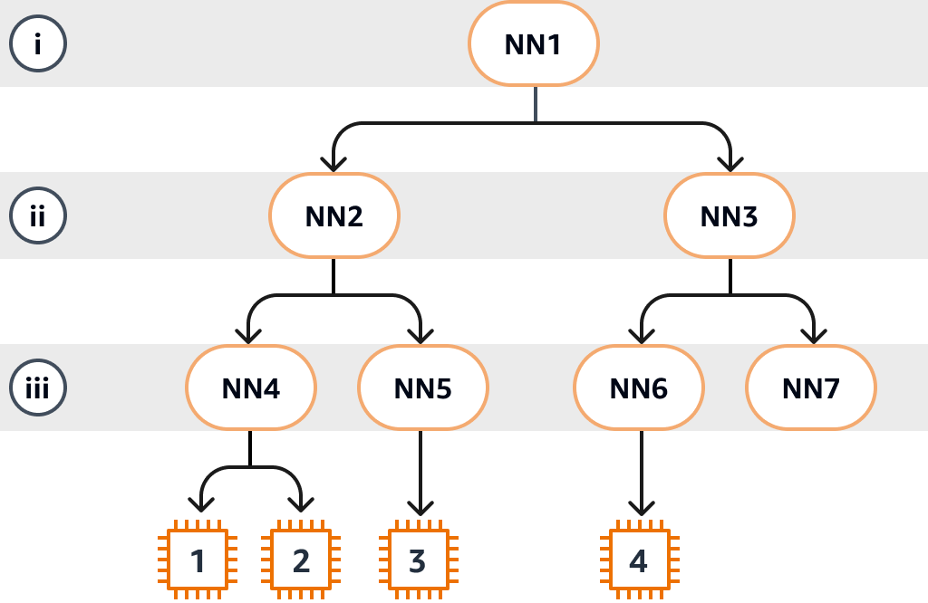
The following diagram provides a visual representation that you can use to understand EC2 topology. The network nodes are identified as NN1 – NN7. The numerals i, ii, and iii identify the network layers. The numbers 1, 2, 3, and 4 identify the EC2 instances. Instances connect to a node in the bottom layer, identified by iii in the following diagram. More than one instance can connect to the same node.
In this example:
-
Instance 1 connects to network node 4 (NN4) in layer iii. NN4 connects to network node 2 (NN2) in layer ii, and NN2 connects to network node 1 (NN1) in layer i, which is the top of the network hierarchy in this example. The network node set comprises NN1, NN2, and NN4, expressed hierarchically from the upper layers to the bottom layer.
-
Instance 2 also connects to network node 4 (NN4). Instance 1 and instance 2 share the same network node set: NN1, NN2, and NN4.
-
Instance 3 connects to network node 5 (NN5). NN5 connects to NN2, and NN2 connects to NN1. The network node set for instance 3 is NN1, NN2, and NN5.
-
Instance 4 connects to network node 6 (NN6). Its network node set is NN1, NN3, and NN6.
When considering the proximity of instances 1, 2, and 3, instances 1 and 2 are closer to each other because they connect to the same network node (NN4), while instance 3 is further away because it connects to a different network node (NN5).
When considering the proximity of all the instances in this diagram, instances 1, 2, and 3 are closer to each other than they are to instance 4 because they share NN2 in their network node set.
As a general rule, if the network node connected to any two instances is the same, these instances are physically close to each other, as is the case with instances 1 and 2. Furthermore, the fewer the number of hops between network nodes, the closer the instances are to each other. For example, instances 1 and 3 have fewer hops to a common network node (NN2) than they have to the network node (NN1) they have in common with instance 4, and are therefore closer to each other than they are to instance 4.
There are no instances running under network node 7 (NN7) in this example, and therefore the API output won't include NN7.
How to interpret the DescribeInstanceTopology output
You can describe the instance topology using the DescribeInstanceTopology API. The output provides a hierarchical view of the underlying network topology for an instance.
The following example output corresponds to the network topology information of the four instances in the preceding diagram. Comments are included in the example output for the purposes of this example.
The following information in the output is important to note:
-
NetworkNodesdescribes the network node set of a single instance. -
In each network node set, the network nodes are listed in hierarchical order from top to bottom.
-
The network node that is connected to the instance is the last network node in the list (the bottom layer).
-
To work out which instances are close to each other, first find common network nodes in the bottom layer. If there are no common network nodes in the bottom layer, then find common network nodes in the upper layers.
In the following example output, i-1111111111example and
i-2222222222example are located closest to each other compared to
the other instances in this example because they have the network node
nn-4444444444example in common in the bottom layer.
Note
The response contains 3 or more network nodes. For information about the number of network nodes in the response for each supported instance type, see Instance types.
{
    "Instances": [
        {
            "InstanceId": "i-1111111111example",  //Corresponds to instance 1
            "InstanceType": "p4d.24xlarge",
            "GroupName": "ML-group",
            "NetworkNodes": [
                "nn-1111111111example",           //Corresponds to NN1 in layer i
                "nn-2222222222example",           //Corresponds to NN2 in layer ii
                "nn-4444444444example"            //Corresponds to NN4 in layer iii - bottom layer, connected to the instance
            ],
            "CapacityBlockId": "null",
            "ZoneId": "usw2-az2",
            "AvailabilityZone": "us-west-2a"
        },
        {
            "InstanceId": "i-2222222222example",  //Corresponds to instance 2
            "InstanceType": "p4d.24xlarge",
            "NetworkNodes": [
                "nn-1111111111example",           //Corresponds to NN1 - layer i
                "nn-2222222222example",           //Corresponds to NN2 - layer ii
                "nn-4444444444example"            //Corresponds to NN4 - layer iii - connected to instance
            ],
            "CapacityBlockId": "null",
            "ZoneId": "usw2-az2",
            "AvailabilityZone": "us-west-2a"
        },
        {
            "InstanceId": "i-3333333333example",  //Corresponds to instance 3
            "InstanceType": "trn1.32xlarge",
            "NetworkNodes": [
                "nn-1111111111example",           //Corresponds to NN1 - layer i
                "nn-2222222222example",           //Corresponds to NN2 - layer ii
                "nn-5555555555example"            //Corresponds to NN5 - layer iii - connected to instance
            ],
            "CapacityBlockId": "null",
            "ZoneId": "usw2-az2",
            "AvailabilityZone": "us-west-2a"
        },
        {
            "InstanceId": "i-444444444example",  //Corresponds to instance 4
            "InstanceType": "trn1.2xlarge",
            "NetworkNodes": [
                "nn-1111111111example",          //Corresponds to NN1 - layer i
                "nn-3333333333example",          //Corresponds to NN3 - layer ii
                "nn-6666666666example"           //Corresponds to NN6 - layer iii - connected to instance
            ],
            "CapacityBlockId": "null",
            "ZoneId": "usw2-az2",
            "AvailabilityZone": "us-west-2a"
        }
    ],
    "NextToken": "SomeEncryptedToken"
}
How to interpret the DescribeCapacityReservationTopology output
You can describe the Capacity Reservation topology using the DescribeCapacityReservationTopology API. The output provides a hierarchical view of the underlying network topology for the reserved capacity.
The following example output corresponds to the network topology information in the preceding diagram. Comments are included in the example output for the purposes of this example.
The following information in the output is important to note:
-
NetworkNodesdescribes the network node set of a single Capacity Reservation. -
In each network node set, the network nodes are listed in hierarchical order from top to bottom.
-
The network node that is connected to the Capacity Reservation is the last network node in the list (the bottom layer).
-
To work out whether Capacity Reservations will be close to each other, first find common network nodes in the bottom layer in the output. If there are no common network nodes in the bottom layer, then find common network nodes in the upper layers.
In the following example output, cr-1111111111example is located on
nn-2222222222example and cr-2222222222example is
located on nn-3333333333example. Because the Capacity Reservations are on different
network nodes in layer ii, communication from instances in one Capacity Reservation to
instances in the other Capacity Reservation will be inefficient.
Note
The response contains 1, 2, or 3 network nodes depending on the type of Capacity Reservation.
{
    "CapacityReservations": [
        {
            "CapacityReservationId": "cr-1111111111example",
            "CapacityBlockId": "null",
            "State": "active",
            "InstanceType": "p4d.24xlarge",
            "NetworkNodes": [
                "nn-1111111111example",      //Corresponds to NN1 - layer i
                "nn-2222222222example"       //Corresponds to NN2 - layer ii
                // Visibility of additional nodes requires an instance launch and
                // the DescribeInstanceTopology API
            ],
            "AvailabilityZone": "us-west-2a"
        },
        {
            "CapacityReservationId": "cr-2222222222example",
            "CapacityBlockId": "null",
            "State": "active",
            "InstanceType": "trn1.2xlarge",
            "NetworkNodes": [
                "nn-1111111111example",      //Corresponds to NN1 - layer i
                "nn-3333333333example"       //Corresponds to NN3 - layer ii
                // Visibility of additional nodes requires an instance launch and
                // the DescribeInstanceTopology API
            ],
            "AvailabilityZone": "us-west-2a"
        }
    ],
    "NextToken": "SomeEncryptedToken"
}
Differences between DescribeInstanceTopology and DescribeCapacityReservationTopology
The following table compares the key differences between the DescribeInstanceTopology and DescribeCapacityReservationTopology APIs:
| Comparison point | DescribeInstanceTopology | DescribeCapacityReservationTopology |
|---|---|---|
| Usage phase | Post-launch (execution mode) | Pre-launch (planning and management mode) |
| Primary purpose | Optimize workloads on running instances |
Capacity planning and Capacity Reservation management (merge, split, assign) before instance launch |
| Number of network nodes |
Shows all nodes for a running instance. If the instance is in a Capacity Reservation, the first nodes will match the corresponding Capacity Reservation topology, followed by additional nodes to connect to the instance. |
Shows a partial set of nodes, which vary based on the Capacity Reservation
state ( |
| State |
Instances must be in |
Capacity Reservations must be in |
| Use cases |
|
|
* For Capacity Blocks for Ultraservers, the network node set is the same when
describing the topology for an active Capacity Reservation or its running instance.
