Elastic Disaster Recovery network diagrams
The following are the network diagrams for AWS Elastic Disaster Recovery :
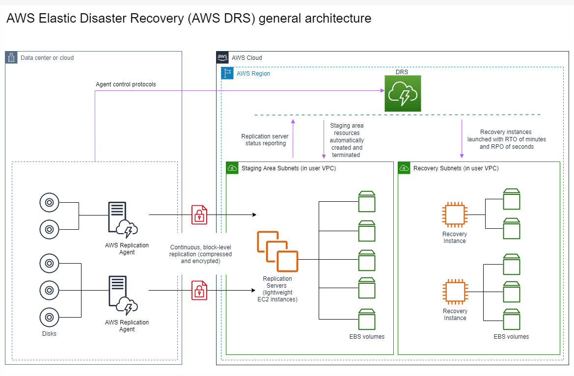
General Architecture - On-Premises to AWS
This diagram shows the general architecture of DRS protecting source servers located in an on-premises environment.
On-Prem to AWS
This diagram shows the network architecture of DRS protecting source servers located in an on-premises environment.

AWS Cloud to AWS Cloud via VPN
This diagram shows the network architecture of DRS protecting source servers located in an on-premises environment. Communication between the on-premise environment and DRS is performed through a VPN connection.

On-Prem to Outposts
This diagram shows the network architecture of DRS protecting source servers located in an on-premises environment. The staging and recovery are both located on AWS Outposts. Find out more about protecting source servers using Outposts.

AWS to Outposts
This diagram shows the network architecture of DRS protecting source servers located in AWS. The staging and recovery are both located on AWS Outposts. Find out more about protecting source servers using Outposts.

On-Premises to AWS Local Zone
This diagram shows the network architecture of DRS protecting source servers located in an on-premises environment. The staging area is located in an AWS Region and the and recovery is in an AWS Local Zone.

AWS Local Zone to Region
This diagram shows the network architecture of DRS protecting source servers located in an AWS Local Zone. The staging and recovery environment are both located in an AWS Region.

AWS Local Zone to AWS Local Zone
This diagram shows the network architecture of DRS protecting source servers located in an AWS Local Zone. The staging environment is located in an AWS Region and the recovery environment is in another AWS Local Zone.

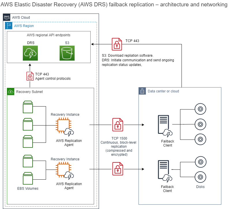
AWS Failback to On-Prem
This diagram shows the network architecture of DRS performing Failback to an on-premise environment after performing a recovery into AWS.