This is version 2.18 of the AWS Elemental Server documentation. This is the latest version. For prior versions, see the Previous Versions section of AWS Elemental Conductor File and AWS Elemental Server Documentation.
Setting Up Audio Channel Mapping with AWS Elemental Server
About this manual
This guide is intended for users who set up transcoding jobs that require moving input audio channels to a different track or channel on the output.
Assumptions
To use this guide, you should be familiar with or understand:
-
How to use AWS Elemental Server web interface to set up and run jobs.
-
How to include audio in your AWS Elemental Server outputs.
-
How to use the REST interface to set up and run AWS Elemental Server jobs when you already know how the REST interface to use the audio mapping feature.
About Audio Mapping
With AWS Elemental Server, you can map audio tracks and channels from your input file to different audio tracks and channels on your output files. You can map any input channel on any input track to any output channel on any output track.
Relevant Terminology
Throughout this document and on the AWS Elemental Server web interface, we use terminology as defined below.
Coding mode (or audio type): The phrases “coding mode” or “audio type” refer to how the audio was recorded and is intended to be played. Supported types of audio are mono, dual mono, stereo, and 5.1 Dolby Digital.
Channels: The smallest unit of audio. For example, a stereo pair consists of left and right channels.
Tracks: A set of channels grouped together is a track.
Audio Stream: All the audio tracks together make up the audio stream.
Stream Assembly: All the streams together (including any of the following: video stream, audio stream, captions, and metadata) make up the stream assembly.
In the AWS Elemental Server web interface, the Stream section contains the encoding instructions that define the outgoing stream assembly. So the Stream section is more correctly the “Stream Assembly” section.
AWS Elemental Server Foundational Audio Concepts
Audio Selectors
AWS Elemental Server manages audio at the track level with Audio Selectors. When you set up your input, you create Audio Selectors to select tracks from the input that are used in a given output.
Input and Output Mapping Matrices
AWS Elemental Server manages audio at the channel level with input and output mapping matrices.
-
You can use an input mapping matrix to reorder the audio channels of one input to match those of another input. This allows you to combine the two files into a single output, one after the other.
-
You can use an output mapping matrix to select a subset of channels from the tracks selected in an Audio Selector and to reorder the audio channels from the input to the output.
Using Multiple Input Files
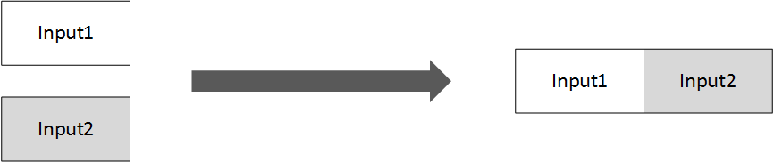
You can provide multiple input files, which AWS Elemental Server combines, one after the other, into a single output file. In the following figure, the two inputs are combined into a single output file that starts with Input 1 and ends with Input 2.
Reordering Audio Channels, Uniform Input - Output Mapping
In versions 2.5 and later of AWS Elemental Server, you can map audio with multiple inputs, provided that all inputs have the same type of audio on the same tracks and channels. You do this by using an output mapping matrix for each of your outputs.
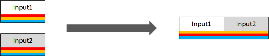
In the following figure, notice the colored bars, which represent channels. Each input file has the same three audio channels in the same position (channel 1, channel 2, and channel 3). The audio on each channel is mapped to a different position in the output: channel 1 on the input becomes channel 2 on the output; channel 2 on the input becomes channel 1 on the output, and channel 3 on the input remains channel 3 on the output.
Reordering Audio Channels, Different Inputs - Input Mapping
In version 2.11 and later, you can also map audio with multiple inputs that have different audio tracks and channels. You do this first by mapping the input tracks and channels into a uniform set using input mapping matrices, then by using the output mapping matrices to specify how you want to audio set up in your output.
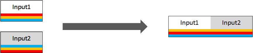
In the following figure, the red channel (channel 1 on Input1 and channel 3 on Input2) is mapped to channel 2 on the output. The yellow channel (channel 2 on Input1 and Input2) is mapped to channel 1 on the output. The blue channel (channel 3 on Input1 and channel 1 on Input 2) is mapped to channel 3 on the output.
You can also use input mapping to exclude a channel from a track. In the following figure, the red channel is present in Input1 but not Input2. For this, you use input mapping matrices, to exclude the red channel from Input1 and to reorder the channels in Input2.
For conceptual descriptions of these options, see Audio Mapping Workflow Examples. For detailed steps to create the mappings using the web interface, see Audio Mapping Procedures.
Prerequisite Information to Setting Up Audio Mapping
Before you set up your audio mapping, plan for it. Know what type of audio you have coming in on your input tracks and channels, for example, stereo or Dolby digital 5.1. Also, identify the tracks and channels of your outputs where you want each type of audio to go.
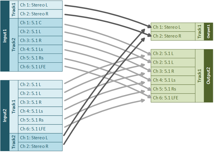
The following figure shows a plan for a mapping with two inputs and two outputs. Of the two inputs, each with two tracks—one containing a stereo pair and one containing 5.1 audio. Each input has the same audio, but in different tracks. Of the two outputs, one has one track containing the stereo pair and the other has one track containing 5.1 audio. Make a similar plan for your own audio inputs and outputs before you begin working with mapping matrices.
Feature Limitations
As you plan your audio output, keep in mind the following restrictions:
-
All channels on each output track must be encoded with the same audio coding mode. For example, your stereo channels must be on a different track than your 5.1 audio. Your input, though, can have multiple audio types on a single track.
-
You can have a maximum of 16 channels per input track and eight channels per output track.
-
You cannot use audio mapping with audio selector groups. If you apply an input mapping matrix to an audio selector that is part of an audio selector group, the matrix is ignored in any output that uses the audio selector group.
Audio Mapping Workflow Examples
This topic shows common mapping use cases and their solutions.
Workflow Example - Identical Input Audio Channels, One Output
Problem
You have two inputs that you want transcoded into a single output, one after the other. The input files have the same type of audio on the same channels. You want the audio channels in the output to be different from the audio channels of the input.
Solution
Use an output mapping matrix to specify how to map the input channels to the output channels.
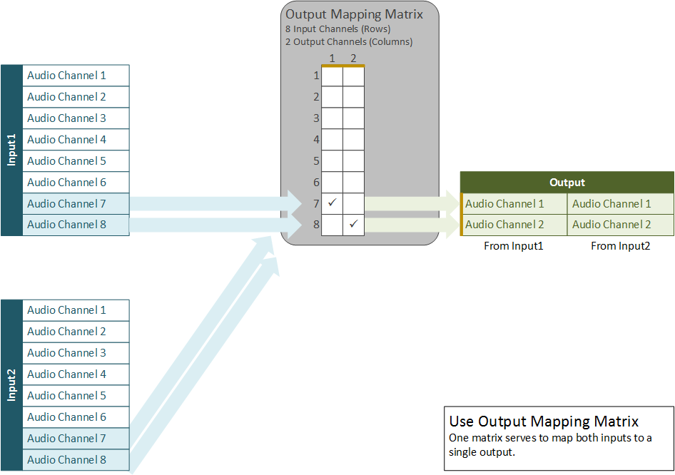
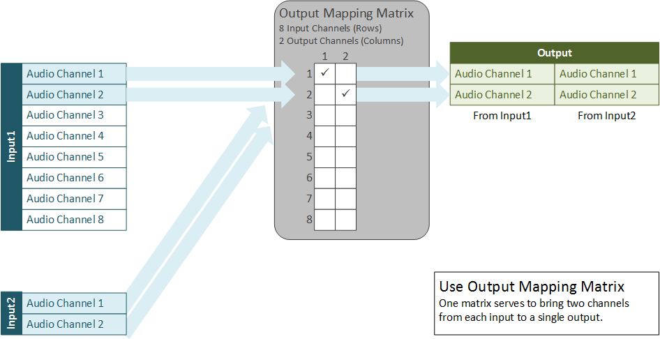
For example, suppose that, in both inputs, you have eight channels coming in on audio track #1. Channels 1-6 are 5.1 audio and channels 7 and 8 are a stereo pair. In your output, you want a single track that contains the stereo pair. To do this, use the following output mapping matrix.
In the mappings, the eight input channels are represented by eight matrix rows and the two output channels are represented by two matrix columns. Notice the yellow bars in the figure below illustrating the relationship between matrix columns and output channels. There are no checkmarks in rows 1 through 6, so the audio on those input channels is ignored and is not used in the output. Row 7 has a checkmark in column 1, so input audio channel 7 is mapped to output audio channel 1. Row 8 has a checkmark in column 2, so input audio channel 8 is mapped to output audio channel 2.
Workflow Example - Identical Input Audio Channels, Two Outputs
Problem
You have two inputs that you want transcoded one after the other into multiple output files. Each output has a different type of audio on each channel. Both inputs have the same type of audio on the same channels.
Solution
Use a different output matrix for each output.
For example, say that, in both inputs, you have eight channels coming in on audio track 1. Channels 1-6 are for 5.1 and channels 7 and 8 form a stereo pair. You want one output with a single track that contains the stereo pair and a second output with a single track that contains six channels for 5.1.
To do this, use two output mapping matrices as shown in the following figure. The mapping matrix for Output1 works exactly as in the example above, with input channels 7 and 8 mapping to output channels 1 and 2, respectively. In the mapping matrix for Output2, eight input channels are represented by eight matrix rows; six output channels are represented by six matrix columns. Input channel 1 maps to output channel 1, Input2 maps to Output2, and so on, through channel 6. Matrix rows 7 and 8 do not have checkmarks, so the audio in these input channels is ignored and does not appear in the output.
Workflow Example - Inputs Have Audio Channels in Different Order
Problem
You have two inputs that you want transcoded into a single file one after the other. Each input has a different type of audio on each channel. Each output has a different type of audio on each channel.
Solution
Use input matrices to map all input channels to the same configuration, then use an output matrix for each output.
For example, suppose that, in both inputs, you have eight channels coming in on audio track 1. In the first input, channels 1-6 are for 5.1 and channels 7 and 8 form a stereo pair. In the second input, channels 1 and 2 form a stereo pair and channels 3-8 are for 5.1. You want one output with a single track that contains the stereo pair and a second output with a single track that contains six channels for 5.1.
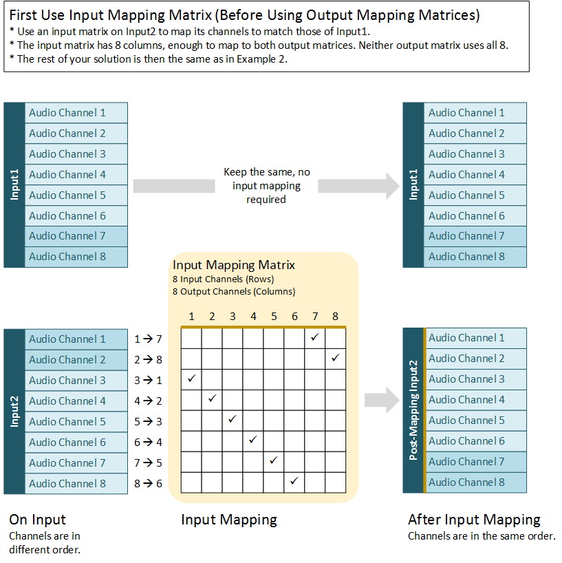
Create a mapping matrix for the second input so that its channels appear in the same order as the first input: The stereo pair maps to channels 7 and 8, and the 5.1 audio maps to channels 1 through 6. You don’t have to create a map for the first input because its channels are already in that order.
In the following figure, notice the yellow bars indicating the relationship between the columns of the input mapping matrix and the channels of the input after mapping.
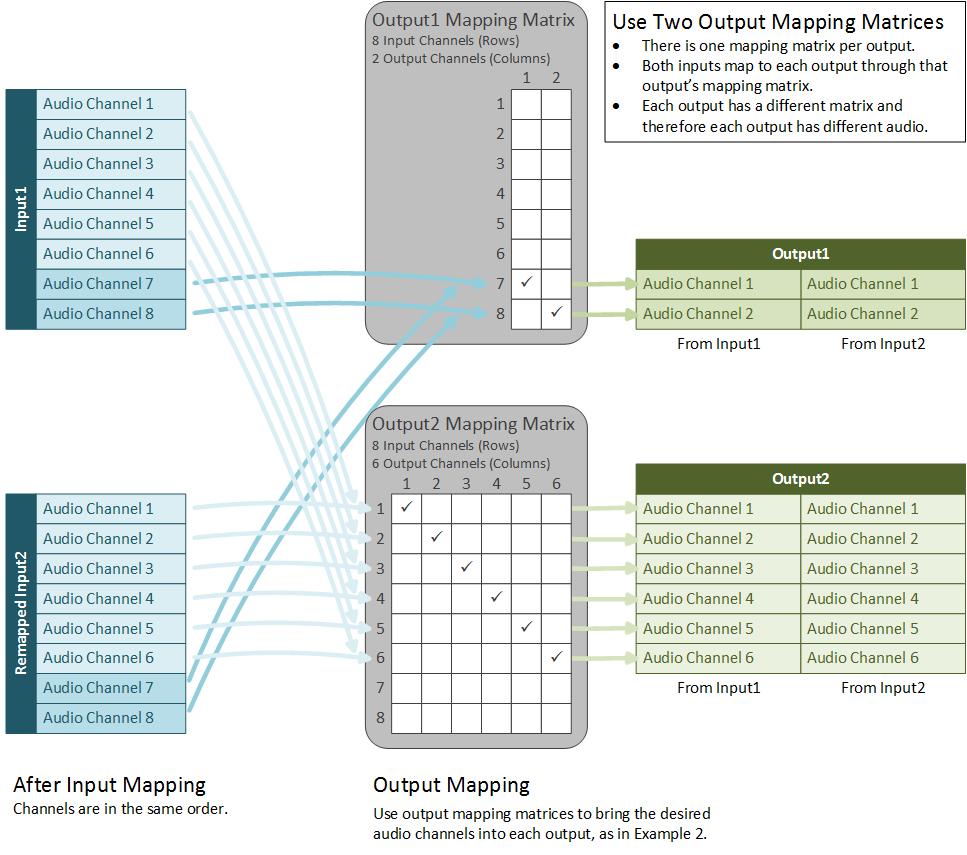
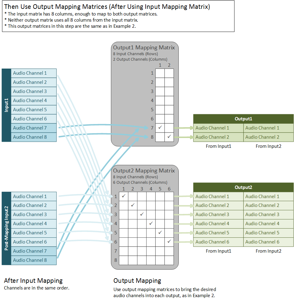
After you have correctly remapped Input2, set up your output matrices as in Workflow Example - Identical Input Audio Channels, Two Outputs. Output1 takes channels 7 and 8 from both Input1 and Input2 and Output2 takes channels 1 through 6 from both Input1and Input2.
The “output” (columns) of the input mapping matrix becomes the “input” (rows) of the output mapping matrix.
Workflow Example - Inputs Have a Different Number of Channels
Problem
You have two inputs that you want transcoded into a single file one after the other. Each input has one track, but with a different number of channels in the track.
Solution
Specify an output matrix in order to select only the desired channels from the input with more channels and to select all the channels from the input with fewer channels. You do not need an input matrix because the channels you do want to use are the same in each input.
For example, suppose that, in one input, you have eight channels coming in on audio track 1. Channels 1 and 2 form a stereo pair and channels 3-8 contain 5.1 audio. In the second input, channels 1 and 2 form a stereo pair. You want one output with a single track that contains a stereo pair. You would use the mapping shown in the following figure.
When to Use Mapping Matrices
Only use an input matrix when you have multiple inputs and the audio channel configurations on the inputs are not the same.
Use an output matrix when you need to do any of the following:
-
Exclude some of your input channels from your output.
-
Reorder the channels in a track, so that the order in the output track is different than in the input track.
-
Split the channels from one input track into more than one output track.
-
Pull individual channels from multiple input tracks into an output track.
Audio Mapping Procedures
This section describes how to set up audio mapping matrices using the web interface. For information on using the REST API to set up audio mapping, see Audio Mapping Using the REST API.
Note
In the examples at Audio Mapping Workflow Examples, mappings are marked with checkmarks. In your actual matrices, use a zero (0) in place of a checkmark. This represents zero gain or passing the full audio from the pre-mapping input channel to the post-mapping input channel.
Map Input Tracks to Output Tracks
Before setting up your input and output mapping matrices, provide information about your incoming audio tracks and specify which of these tracks to include in which output:
-
Create one Audio Selector for each incoming audio track you are using.
-
Associate the Audio Selector with a specific input track by providing the track number or numbers.
-
For each output with a distinct audio setup, create a Stream and add Audio tabs (one tab per track on the output).
-
Select an Audio Selector from the dropdown list on each tab.
-
Create at least one Output and apply the Stream to it.
Create Input Matrices
Only use an input matrix when you have multiple inputs and the audio channel configurations on the inputs are not the same.
The purpose of input matrices is to make the channels in each input match each other, as shown in Workflow Example - Inputs Have Audio Channels in Different Order. After mapping, each channel in each input will have the same type of audio information, like an audio pair on channels 7 and 8.
Perform this step in the Input section of the web interface, in the Audio Selector subsection.
Notes on Input Matrices
The following requirements apply to all input matrices:
-
Each input matrix must have the same number of columns. That is, the set of channels being mapped to must be the same for each input. This provides a uniform set of inputs for the output matrices.
-
Each input matrix must have at least enough columns to accommodate the output matrix with the most number of rows. For example, if you have an output matrix with two rows and an output matrix with six rows, each input matrix must have at least six columns.
Input Matrix Procedure - Inputs Section
| Number in the graphic | Description |
|---|---|
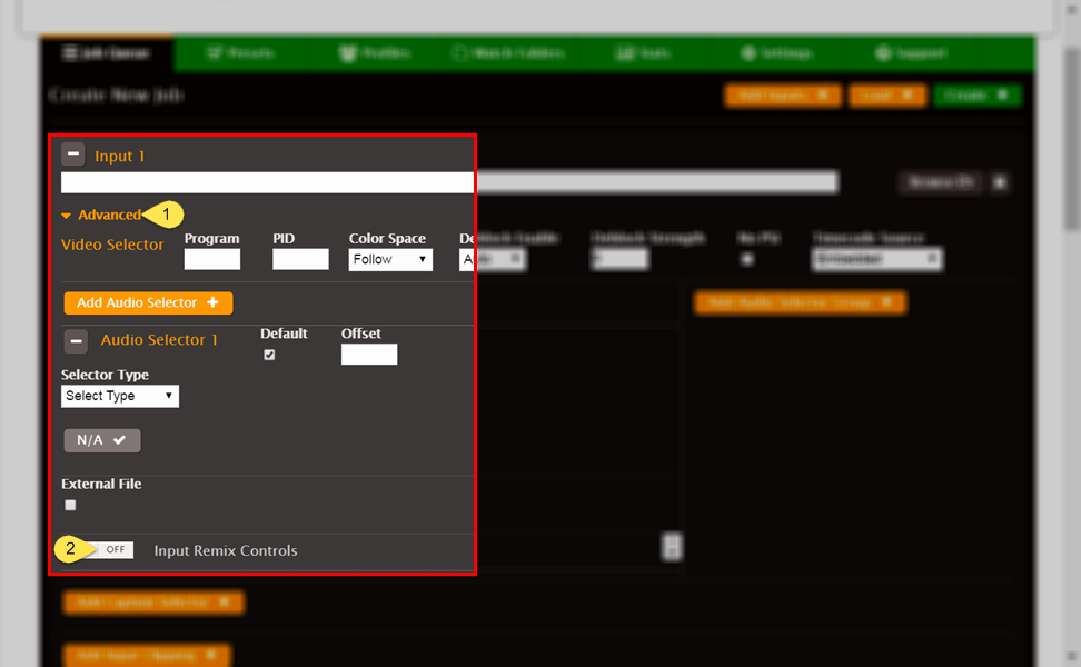
| 1 | If the Advanced section of the Input is collapsed, click Advanced to open it. |
| 2 | Click the Input Remix Controls to access the input Channel Mapping matrix. |
| Number in the graphic | Description |
|---|---|
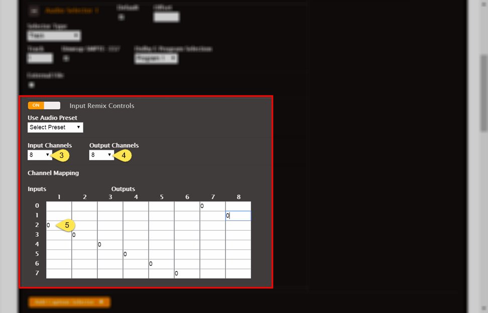
| 3 | Choose the number of input channels in the track from the Input Channels dropdown. |
| 4 | Choose the number of channels that will be passed into the output from the Output Channels dropdown. |
| 5 |
In each row of the matrix (which corresponds to an input channel before mapping), use a zero to mark a column. Each column corresponds to an input channel after mapping. In the example pictured above, pre-mapping input channel 3 is being mapped to post-mapping input channel 1. |
Note
On input mapping matrices, rows are labeled starting at zero. Therefore, you map channel 1 on row 0, channel 2 on row 1, and so forth.
Create Output Matrices
Use an output matrix when you need to do any of the following:
-
Exclude some of your input channels from your output.
-
Reorder the channels in a track, so that the order in the output track is different than in the input track.
-
Split the channels from one input track into more than one output track.
-
Pull individual channels from multiple input tracks into an output track.
If you have multiple inputs with channels that are numbered differently, before you map them to the outputs, map them to uniformity following the guidance in Create Input Matrices. Use output matrices just to map uniformly numbered input channels to output channels.
Output Matrix Procedure - Streams Section
In output mapping matrices, rows are labeled starting at 1 and columns are labeled starting at 0. So you map input channel 1 in row 0, input channel 2 in row 1, and so on. You map to output channel 1 in column 1, output channel 2 in column 2, and so on.
The following screenshot and UI element descriptions describe what to do to fill in an output matrix.
| Number in the graphic | Description |
|---|---|
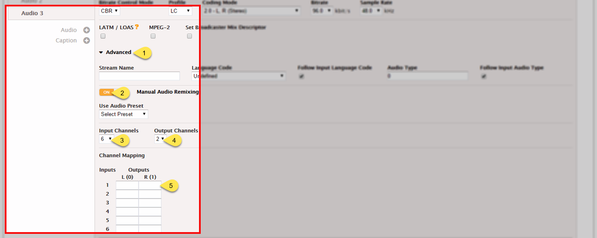
| 1 | From the Audio tab corresponding to the track you are working with, click Advanced. |
| 2 | Click the Manual Audio Remixing slider. |
| 3 | Select the number of channels coming from your input. In the example of a 5.1 audio track, you would pick 6. Channels 1–6 correspond to the numbers 0–5 on the matrix. |
| 4 | Select the number of channels you want in your output track. For example, to map the first two channels of the 5.1 audio to a stereo pair, you would pick 2. Channels 1 and 2 correspond to 0 and 1 on the matrix. |
| 5 |
In each row of the matrix (which corresponds to an input channel) use a zero to mark a column (which corresponds to an output channel). Zero refers to zero db of gain or passing through the full audio. You can do audio remixing using other values. Audio remixing is beyond the scope of this document. In the example shown, input channel 1 (row 1) is mapped to output channel 1 (column 0) and input channel 2 (row 1) is mapped to output channel 2 (column 1). Input channels 3 through 6 are muted out and not passed to the output. |
Audio Mapping Using the REST API
This section provides information for implementing audio mapping using the API.
To use this guidance, you should have a basic understanding of the following:
-
The conceptual information provided in the main body of this document.
-
Creating and modifying jobs using XML.
Audio Mapping XML Reference Tables
The XML element for audio mapping, <remix_settings>, is structurally the
same for input mapping and output mapping. The differences are the location of the element and
the valid range for the child element, <channels_out>.
| Element | Notes | |
|---|---|---|
audio_selector |
Corresponds to the Audio Selector section of the UI, under Input > Advanced |
|
order |
This is the number of the audio selector within the input. It is not unique and does not function as an ID. The value of <order> increments from one within each <audio_selector> element. |
|
name |
The name used for assigning an Audio Selector to an <audio_description> element. | |
selector_type |
The selector type used for the value “track”. | |
track |
The track numbers of the input tracks being selected. Provide these as a string of comma-separated integers. |
|
remix_settings |
The settings used to create an input mapping matrix. Place <remix_settings> here, as a child of <audio_selector>. | |
| Element | Notes | ||
|---|---|---|---|
name |
The element that is used to map a stream assembly to an output. The value of this element must match the value of the child element <stream_assembly_name> of the associated output. | ||
audio_description |
The description of the one <audio_description> element per output track. | ||
<codec_settings> |
Use the codec name in place of “codec”. Supported
options are: aac, mp2, wma2,
wav, aiff, ac3,
ec3, pass through, and
dtse. |
||
coding_mode |
Metadata on how the audio is encoded on this track. AWS Elemental Server supports one type of audio coding per output track. Valid range: 1_0, 1_1, 2_0, 5_1, ad_receiver_mix 1_0: Mono 1_1: Dual Mono 2_0: Stereo 5_1: 5.1 Dolby Digital |
||
remix_settings |
Placement of <remix_settings> here, as a child of
<audio_description>, creates an output mapping matrix. |
||
audio_source_name |
The audio source name to use to associate the output audio track with an Audio Selector. | ||
| Element | Notes | |
|---|---|---|
output |
The setting which represents the actual set of streams delivered to a destination address. | |
stream_assembly_name |
The name to use to associate a stream with an output. | |
<remix_settings> in Output Mapping
For output mapping, include the <remix_settings> element as a child of
<audio_description>.
| Element | Notes | |
|---|---|---|
audio_description |
There is one <audio_description> element per output track. |
|
remix_settings |
Placement <remix_settings> here creates an output mapping
matrix |
|
| Element | Type | Description | Notes | ||
|---|---|---|---|---|---|
channels_in |
integer | Number of channels in input track. |
Valid range: 1 – 16 This number is the same for all inputs. |
||
channels_out |
integer | Number of channels in output track. |
Valid range: 1 – 8 AWS Elemental Server supports up to eight channels per output track. You must specify the correct number of output channels for the <coding_mode> value you provide. For example, 5.1 audio accepts six channels. |
||
channel_mapping |
XML | Element containing all the mapping matrix data. | Corresponds to the table matrix in the UI. | ||
out_ch_n |
Audio data for one output channel. | Each <out_ch_n> element represents an output channel. |
Each n is an integer that represents the matrix column number. NOTE:n counts from zero, so the channel number is (n + 1). |
||
in_ch_m |
integer |
The amount of audio from the input channel that is passed into the output channel in dB gain.
|
Valid range: -60 to 60 0: Pass through audio at same level as input -60: Mute channel Each m is an integer that represents the matrix row number. The number of NOTE:m counts from zero, so the channel number is (m + 1). |
||
<remix_settings> Input Mapping
For input mapping, include the <remix_settings> element as a child of
<audio_selector>. The <audio_selector> corresponds to the
Audio Selector section of the web UI. Both represent an input audio
track.
| Element | Notes |
|---|---|
audio_selector |
The setting which represents the audio information for a single track from the input. Placement of the |
| Element | Type | Description | Notes | ||
|---|---|---|---|---|---|
channels_in |
integer | Integer which shows the number of pre-mapping input channels. | Valid range: 1 - 16 | ||
channels_out |
integer | Integer which shows the number of post-mapping input channels. |
Valid range: 1 – 16 Each output may use a different subset of these channels. |
||
channel_mapping |
Mapping data | Element which contains all the mapping matrix data. | Corresponds to the table matrix in the UI. | ||
out_ch_n |
Audio data for one post-mapped channel. | Each <out_ch_n> element represents
an input channel after it has been mapped. |
Each <out_ch_n> element corresponds to a column in the UI table. n is an integer that represents the column number. Increment from zero to one less than the value of <channels_out>. |
||
in_ch_m |
integer | The amount of audio from a pre-mapping input channel that is passed into the new post-mapping input channel. |
Valid range: -60 to 60 Each m is an integer that represents the row number.
Increment from zero to one less than the value of In each out_ch_n element, should be one of these for each channel in the incoming audio track. |
||
Example XML
Examples in this section correspond to the examples provided in Audio Mapping Workflow Examples.
XML Example - Identical Input Audio Channels, One Output
This example shows the relevant sections of the XML body for the job in Workflow Example - Identical Input Audio Channels, One Output.
This job uses an output matrix to select channels 7 and 8 only from an 8-channel track. Two inputs have this same track. The output has a single, 2-channel track.
The following shows the <remix_settings> element, which contains the
elements required for output audio mapping and audio remixing.
In this example, <remix_settings> is a child of
<job>/<stream_assembly>/<audio_description> because it represents an
output mapping matrix.
<remix_settings>
   <channels_in>8</channels_in>                                         //8 channels coming in
   <channels_out>2</channels_out>                                       //2 channels going out
This is the <channel_mapping> element, which corresponds to the output
mapping matrix.
	<channel_mapping>
	  <out_ch_0>
		<in_ch_0>-60</in_ch_0>
		<in_ch_1>-60</in_ch_1>
		<in_ch_2>-60</in_ch_2>
		<in_ch_3>-60</in_ch_3>
		<in_ch_4>-60</in_ch_4>
		<in_ch_5>-60</in_ch_5>
		<in_ch_6>0</in_ch_6>	//Input channel 7 is passed into output channel 1
		<in_ch_7>-60</in_ch_7>
	  </out_ch_0>
	  <out_ch_1>
		<in_ch_0>-60</in_ch_0>
		<in_ch_1>-60</in_ch_1>
		<in_ch_2>-60</in_ch_2>
		<in_ch_3>-60</in_ch_3>
		<in_ch_4>-60</in_ch_4>
		<in_ch_5>-60</in_ch_5>
		<in_ch_6>-60</in_ch_6>
		<in_ch_7>0</in_ch_7>	//Input channel 8 is passed into output channel 2
	  </out_ch_1>
	</channel_mapping>
</remix_settings>
XML Example - Identical Input Audio Channels, Two Outputs
This example shows the relevant sections of the XML body for the job in Workflow Example - Identical Input Audio Channels, Two Outputs.
This job uses two output matrices in two separate stream assemblies to set up audio for two outputs. The first mapping matrix is the same as the one in XML Example - Identical Input Audio Channels, One Output. The second mapping matrix takes only channels 1-6 from the eight input channels and maps them to a 6-channel track on the second output.
The following shows the first <stream_assembly> element, which is applied
to an output element. It is a child of the top-level element, <job>.
<stream_assembly>
    <name>stream_assembly_0</name>
      <audio_description>
      .
      .
      .
            <aac_settings>
              .
              .
              .
              <coding_mode>2_0</coding_mode>
              .
              .
              .
            </aac_settings>
            <remix_settings>
               .			//Same as in Example 1
               .
               .
            </remix_settings>
            .
            .
            .
            <audio_source_name>Audio Selector 1</audio_source_name>
            .
            .
            .
       </audio_description>
</stream_assembly>
The following is the second <stream_assembly> element, which is applied to
a different output element.
<stream_assembly>
    <name>stream_assembly_1</name>
      <audio_description>
            .
            .
            .
            <aac_settings>
              .
              .
              .
              <coding_mode>5_1</coding_mode>
              .
              .
              .
            </aac_settings>
            <remix_settings>
              <channels_in>8</channels_in>	//8 channels coming in
              <channels_out>6</channels_out>	//6 channels going out
The following is the <channel_mapping> element that corresponds to the
second output mapping matrix. The stereo pair (<in_ch_6> and
<in_ch_7>) are muted out on all output channels.
              <channel_mapping>
                <out_ch_0>
                  <in_ch_0>0</in_ch_0>	//Input channel 1 is passed into output channel 1
                  <in_ch_1>-60</in_ch_1>
                  <in_ch_2>-60</in_ch_2>
                  <in_ch_3>-60</in_ch_3>
                  <in_ch_4>-60</in_ch_4>
                  <in_ch_5>-60</in_ch_5>
                  <in_ch_6>-60</in_ch_6>
                  <in_ch_7>-60</in_ch_7>
                </out_ch_0>
                <out_ch_1>
                  <in_ch_0>-60</in_ch_0>
                  <in_ch_1>0</in_ch_1>	//Input channel 2 is passed into output channel 2
                  <in_ch_2>-60</in_ch_2>
                  <in_ch_3>-60</in_ch_3>
                  <in_ch_4>-60</in_ch_4>
                  <in_ch_5>-60</in_ch_5>
                  <in_ch_6>-60</in_ch_6>
                  <in_ch_7>-60</in_ch_7>
                </out_ch_1>
                <out_ch_2>
                  <in_ch_0>-60</in_ch_0>
                  <in_ch_1>-60</in_ch_1>
                  <in_ch_2>0</in_ch_2>	//Input channel 3 is passed into output channel 3
                  <in_ch_3>-60</in_ch_3>
                  <in_ch_4>-60</in_ch_4>
                  <in_ch_5>-60</in_ch_5>
                  <in_ch_6>-60</in_ch_6>
                  <in_ch_7>-60</in_ch_7>
                </out_ch_2>
                <out_ch_3>
                  <in_ch_0>-60</in_ch_0>
                  <in_ch_1>-60</in_ch_1>
                  <in_ch_2>-60</in_ch_2>
                  <in_ch_3>0</in_ch_3>	//Input channel 4 is passed into output channel 4
                  <in_ch_4>-60</in_ch_4>
                  <in_ch_5>-60</in_ch_5>
                  <in_ch_6>-60</in_ch_6>
                  <in_ch_7>-60</in_ch_7>
                </out_ch_3>
                <out_ch_4>
                  <in_ch_0>-60</in_ch_0>
                  <in_ch_1>-60</in_ch_1>
                  <in_ch_2>-60</in_ch_2>
                  <in_ch_3>-60</in_ch_3>
                  <in_ch_4>0</in_ch_4>	//Input channel 5 is passed into output channel 5
                  <in_ch_5>-60</in_ch_5>
                  <in_ch_6>-60</in_ch_6>
                  <in_ch_7>-60</in_ch_7>
                </out_ch_4>
                <out_ch_5>
                  <in_ch_0>-60</in_ch_0>
                  <in_ch_1>-60</in_ch_1>
                  <in_ch_2>-60</in_ch_2>
                  <in_ch_3>-60</in_ch_3>
                  <in_ch_4>-60</in_ch_4>
                  <in_ch_5>0</in_ch_5>	//Input channel 6 is passed into output channel 6
                  <in_ch_6>-60</in_ch_6>
                  <in_ch_7>-60</in_ch_7>
                </out_ch_5>
              </channel_mapping>
            </remix_settings>
            .
            .
            .
            .
      </audio_description>
</stream_assembly>
The following is the first <output> element, which we associate with the
first stream assembly, so the stereo pair ends up on this output. In this example, both outputs
are children of the same <output_group> element. <output_group>
is a child of <job>.
<output_group>
  .
  .
  .
  <output>
            .
            .
            .
    <stream_assembly_name>stream_assembly_0</stream_assembly_name>
            .
            .
            .
  </output>
The following is the second <output> element, which we associate with the
second stream assembly, so the 5.1 audio ends up on this output.
  <output>
            .
            .
            .
    <stream_assembly_name>stream_assembly_1</stream_assembly_name>
            .
            .
            .
  </output>
</output_group>
XML Example - Inputs Have Audio Channels in Different Order
This example shows the relevant sections of the XML body for the job in Workflow Example - Inputs Have Audio Channels in Different Order.
This job takes two inputs, both with stereo and 5.1 audio. Each input has the audio on different channels. To bring the inputs together, this job uses an input mapping matrix on the second input that reorders its channels to match the first input. This job creates two outputs, each with different audio, by using an output mapping matrix for each output, like XML Example - Identical Input Audio Channels, Two Outputs.
The following shows the first <input> element, which does not have any
input mapping elements. This element is a child of the top-level element,
<job>.
<input>
    .
    .
    .
    <order>1</order>
    .
    .
    .
    <name>input_1</name>
    .
    .
    .
</input>
The following is the second <input> element, which does have input mapping
elements.
<input>
    .
    .
    .
    <order>2</order>
    .
    .
    .
    <name>input_2</name>
        .
        .
        .
The following is the <remix_settings> element that is a child of the
second <input element>. This <remix_settings> element contains
all the input mapping elements. In this case, <remix_settings> is a child of
<job>/<input>/<audio_selector> because it represents an input mapping
matrix.
      <remix_settings>
        <channels_in>8</channels_in>	//8 original input channels
        <channels_out>8</channels_out>	//8 remapped input channels, in a new order
        <channel_mapping>
          <out_ch_0>
            <in_ch_0>-60</in_ch_0>
            <in_ch_1>-60</in_ch_1>
            <in_ch_2>-60</in_ch_2>
            <in_ch_3>-60</in_ch_3>
            <in_ch_4>-60</in_ch_4>
            <in_ch_5>-60</in_ch_5>
            <in_ch_6>0</in_ch_6>	//Input channel 7 is being passed into new input channel 1
            <in_ch_7>-60</in_ch_7>
          </out_ch_0>
          <out_ch_1>
            <in_ch_0>-60</in_ch_0>
            <in_ch_1>-60</in_ch_1>
            <in_ch_2>-60</in_ch_2>
            <in_ch_3>-60</in_ch_3>
            <in_ch_4>-60</in_ch_4>
            <in_ch_5>-60</in_ch_5>
            <in_ch_6>-60</in_ch_6>
            <in_ch_7>0</in_ch_7>	//Input channel 8 is being passed into new input channel 2
          </out_ch_1>
          <out_ch_2>
            <in_ch_0>0</in_ch_0>	//Input channel 1 is being passed into new input channel 3
            <in_ch_1>-60</in_ch_1>
            <in_ch_2>-60</in_ch_2>
            <in_ch_3>-60</in_ch_3>
            <in_ch_4>-60</in_ch_4>
            <in_ch_5>-60</in_ch_5>
            <in_ch_6>-60</in_ch_6>
            <in_ch_7>-60</in_ch_7>
          </out_ch_2>
          .
          .
          .
          <out_ch_7>
            <in_ch_0>-60</in_ch_0>
            <in_ch_1>-60</in_ch_1>
            <in_ch_2>-60</in_ch_2>
            <in_ch_3>-60</in_ch_3>
            <in_ch_4>-60</in_ch_4>
            <in_ch_5>0</in_ch_5>	//Input channel 6 is being passed into new input channel 8
            <in_ch_6>-60</in_ch_6>
            <in_ch_7>-60</in_ch_7>
          </out_ch_7>
        </channel_mapping>
      </remix_settings>
    .
    .
    .
    </audio_selector>
</input>
The following is the first <stream_assembly> element, which is applied to
an output element in the following listing. It contains the same audio channel mapping
instructions in the remix settings as Workflow Example - Identical Input
Audio Channels, One Output. It is a child of the top-level
element, <job>.
<stream_assembly>
    <name>stream_assembly_0</name>
      <audio_description>
      .
      .
      .
            <aac_settings>
              .
              .
              .
              <coding_mode>2_0</coding_mode>
              .
              .
              .
            </aac_settings>
            <remix_settings>
               .
               .
               .
            </remix_settings>
            .
            .
            .
            <audio_source_name>Audio Selector 1</audio_source_name>
            .
            .
            .
       </audio_description>
</stream_assembly>
The following is the second <stream_assembly> element, which is applied to
a different output element. It contains the same audio channel mapping instructions and remix
settings as in XML Example - Identical Input Audio
Channels, Two Outputs.
<stream_assembly>
    <name>stream_assembly_1</name>
      <audio_description>
            .
            .
            .
            <aac_settings>
              .
              .
              .
              <coding_mode>5_1</coding_mode>
              .
              .
              .
            </aac_settings>
            <remix_settings>
               .
               .
               .
            </remix_settings>
            .
            .
            .
            <audio_source_name>Audio Selector 1</audio_source_name>
            .
            .
            .
          </audio_description>
</stream_assembly>
The following is the first <output> element, which we associate with the
first stream assembly, so the stereo pair ends up on this output. In this example, both outputs
are children of the same <output_group> and <output_group> is a
child of <job>.
<output_group>
  .
  .
  .
  <output>
            .
            .
            .
    <stream_assembly_name>stream_assembly_0</stream_assembly_name>
            .
            .
            .
  </output>
The following is the second <output> element, which we associate with the
second stream assembly, so the 5.1 audio ends up on this output.
  <output>
            .
            .
            .
    <stream_assembly_name>stream_assembly_1</stream_assembly_name>
            .
            .
            .
  </output>
</output_group>
