기계 번역으로 제공되는 번역입니다. 제공된 번역과 원본 영어의 내용이 상충하는 경우에는 영어 버전이 우선합니다.
SDK에서 회로 구성
이 섹션에서는 회로 정의, 사용 가능한 게이트 보기, 회로 확장, 각 디바이스가 지원하는 게이트 보기의 예를 제공합니다. 또한를 수동으로 할당하고qubits, 컴파일러에 정의된 대로 정확하게 회로를 실행하도록 지시하고, 노이즈 시뮬레이터를 사용하여 노이즈가 많은 회로를 빌드하는 방법에 대한 지침도 포함되어 있습니다.
특정 QPUs. 자세한 내용은 Amazon Braket의 펄스 제어를 참조하세요.
게이트 및 회로
양자 게이트 및 회로는 Amazon Braket Python SDK의 braket.circuitsCircuit().
예: 회로 정의
이 예제는 표준, 단일 쿼트 Hadamard 게이트 및 2쿼트 q1CNOT 게이트로 구성된 4개qubits(q0, q2, 및 레이블 지정q3)의 샘플 회로를 정의하는 것으로 시작합니다. 다음 예제와 같이 print 함수를 호출하여이 회로를 시각화할 수 있습니다.
# Import the circuit module
from braket.circuits import Circuit

# Define circuit with 4 qubits
my_circuit = Circuit().h(range(4)).cnot(control=0, target=2).cnot(control=1, target=3)
print(my_circuit)
T  : │  0  │     1     │
      ┌───┐
q0 : ─┤ H ├───●─────────
      └───┘   │
      ┌───┐   │
q1 : ─┤ H ├───┼─────●───
      └───┘   │     │
      ┌───┐ ┌─┴─┐   │
q2 : ─┤ H ├─┤ X ├───┼───
      └───┘ └───┘   │
      ┌───┐       ┌─┴─┐
q3 : ─┤ H ├───────┤ X ├─
      └───┘       └───┘
T  : │  0  │     1     │
예: 파라미터화된 회로 정의
이 예제에서는 자유 파라미터에 의존하는 게이트가 있는 회로를 정의합니다. 이러한 파라미터의 값을 지정하여 새 회로를 생성하거나 회로를 제출할 때 특정 디바이스에서 양자 작업으로 실행할 수 있습니다.
from braket.circuits import Circuit, FreeParameter

# Define a FreeParameter to represent the angle of a gate
alpha = FreeParameter("alpha")

# Define a circuit with three qubits
my_circuit = Circuit().h(range(3)).cnot(control=0, target=2).rx(0, alpha).rx(1, alpha)
print(my_circuit)
다음과 같이 각 파라미터의 값을 지정하는 단일float(모든 자유 파라미터가 취하는 값) 또는 키워드 인수를 회로에 제공하여 파라미터화되지 않은 새 회로를 파라미터화된 회로에서 생성할 수 있습니다.
my_fixed_circuit = my_circuit(1.2)
my_fixed_circuit = my_circuit(alpha=1.2)
print(my_fixed_circuit)
my_circuit는 수정되지 않으므로 이를 사용하여 고정된 파라미터 값으로 많은 새 회로를 인스턴스화할 수 있습니다.
예: 회로의 게이트 수정
다음 예제에서는 제어 및 전원 한정자를 사용하는 게이트가 있는 회로를 정의합니다. 이러한 수정 사항을 사용하여 제어된 게이트와 같은 새 Ry 게이트를 생성할 수 있습니다.
from braket.circuits import Circuit

# Create a bell circuit with a controlled x gate
my_circuit = Circuit().h(0).x(control=0, target=1)

# Add a multi-controlled Ry gate of angle .13
my_circuit.ry(angle=.13, target=2, control=(0, 1))

# Add a 1/5 root of X gate
my_circuit.x(0, power=1/5)

print(my_circuit)
게이트 한정자는 로컬 시뮬레이터에서만 지원됩니다.
예: 사용 가능한 모든 게이트 보기
다음 예제에서는 Amazon Braket에서 사용 가능한 모든 게이트를 보는 방법을 보여줍니다.
from braket.circuits import Gate
# Print all available gates in Amazon Braket
gate_set = [attr for attr in dir(Gate) if attr[0].isupper()]
print(gate_set)
이 코드의 출력에는 모든 게이트가 나열됩니다.
['CCNot', 'CNot', 'CPhaseShift', 'CPhaseShift00', 'CPhaseShift01', 'CPhaseShift10', 'CSwap', 'CV', 'CY', 'CZ', 'ECR', 'GPhase', 'GPi', 'GPi2', 'H', 'I', 'ISwap', 'MS', 'PRx', 'PSwap', 'PhaseShift', 'PulseGate', 'Rx', 'Ry', 'Rz', 'S', 'Si', 'Swap', 'T', 'Ti', 'U', 'Unitary', 'V', 'Vi', 'X', 'XX', 'XY', 'Y', 'YY', 'Z', 'ZZ']
이러한 게이트는 해당 유형의 회로에 대한 메서드를 호출하여 회로에 추가할 수 있습니다. 예를 들어 circ.h(0)를 호출하여 첫 번째에 하다마드 게이트를 추가합니다qubit.
참고
게이트가 제자리에 추가되고 다음 예제에서는 이전 예제에 나열된 모든 게이트를 동일한 회로에 추가합니다.
circ = Circuit()
# toffoli gate with q0, q1 the control qubits and q2 the target.
circ.ccnot(0, 1, 2)
# cnot gate
circ.cnot(0, 1)
# controlled-phase gate that phases the |11> state, cphaseshift(phi) = diag((1,1,1,exp(1j*phi))), where phi=0.15 in the examples below
circ.cphaseshift(0, 1, 0.15)
# controlled-phase gate that phases the |00> state, cphaseshift00(phi) = diag([exp(1j*phi),1,1,1])
circ.cphaseshift00(0, 1, 0.15)
# controlled-phase gate that phases the |01> state, cphaseshift01(phi) = diag([1,exp(1j*phi),1,1])
circ.cphaseshift01(0, 1, 0.15)
# controlled-phase gate that phases the |10> state, cphaseshift10(phi) = diag([1,1,exp(1j*phi),1])
circ.cphaseshift10(0, 1, 0.15)
# controlled swap gate
circ.cswap(0, 1, 2)
# swap gate
circ.swap(0,1)
# phaseshift(phi)= diag([1,exp(1j*phi)])
circ.phaseshift(0,0.15)
# controlled Y gate
circ.cy(0, 1)
# controlled phase gate
circ.cz(0, 1)
# Echoed cross-resonance gate applied to q0, q1
circ = Circuit().ecr(0,1)
# X rotation with angle 0.15
circ.rx(0, 0.15)
# Y rotation with angle 0.15
circ.ry(0, 0.15)
# Z rotation with angle 0.15
circ.rz(0, 0.15)
# Hadamard gates applied to q0, q1, q2
circ.h(range(3))
# identity gates applied to q0, q1, q2
circ.i([0, 1, 2])
# iswap gate, iswap = [[1,0,0,0],[0,0,1j,0],[0,1j,0,0],[0,0,0,1]]
circ.iswap(0, 1)
# pswap gate, PSWAP(phi) = [[1,0,0,0],[0,0,exp(1j*phi),0],[0,exp(1j*phi),0,0],[0,0,0,1]]
circ.pswap(0, 1, 0.15)
# X gate applied to q1, q2
circ.x([1, 2])
# Y gate applied to q1, q2
circ.y([1, 2])
# Z gate applied to q1, q2
circ.z([1, 2])
# S gate applied to q0, q1, q2
circ.s([0, 1, 2])
# conjugate transpose of S gate applied to q0, q1
circ.si([0, 1])
# T gate applied to q0, q1
circ.t([0, 1])
# conjugate transpose of T gate applied to q0, q1
circ.ti([0, 1])
# square root of not gate applied to q0, q1, q2
circ.v([0, 1, 2])
# conjugate transpose of square root of not gate applied to q0, q1, q2
circ.vi([0, 1, 2])
# exp(-iXX theta/2)
circ.xx(0, 1, 0.15)
# exp(i(XX+YY) theta/4), where theta=0.15 in the examples below
circ.xy(0, 1, 0.15)
# exp(-iYY theta/2)
circ.yy(0, 1, 0.15)
# exp(-iZZ theta/2)
circ.zz(0, 1, 0.15)
# IonQ native gate GPi with angle 0.15 applied to q0
circ.gpi(0, 0.15)
# IonQ native gate GPi2 with angle 0.15 applied to q0
circ.gpi2(0, 0.15)
# IonQ native gate MS with angles 0.15, 0.15, 0.15 applied to q0, q1
circ.ms(0, 1, 0.15, 0.15, 0.15)
사전 정의된 게이트 세트 외에도 자체 정의된 단일 게이트를 회로에 적용할 수도 있습니다. 이는 단일 쿼트 게이트(다음 소스 코드에 표시됨) 또는 targets 파라미터에 의해 qubits 정의된에 적용된 다중 쿼트 게이트일 수 있습니다.
import numpy as np

# Apply a general unitary
my_unitary = np.array([[0, 1],[1, 0]])
circ.unitary(matrix=my_unitary, targets=[0])
예: 기존 회로 확장
지침을 추가하여 기존 회로를 확장할 수 있습니다. Instruction는 양자 디바이스에서 수행할 양자 작업을 설명하는 양자 명령입니다. Instruction 연산자에는 유형의 객체Gate만 포함됩니다.
# Import the Gate and Instruction modules
from braket.circuits import Gate, Instruction

# Add instructions directly.
circ = Circuit([Instruction(Gate.H(), 4), Instruction(Gate.CNot(), [4, 5])])

# Or with add_instruction/add functions
instr = Instruction(Gate.CNot(), [0, 1])
circ.add_instruction(instr)
circ.add(instr)

# Specify where the circuit is appended
circ.add_instruction(instr, target=[3, 4])
circ.add_instruction(instr, target_mapping={0: 3, 1: 4})

# Print the instructions
print(circ.instructions)
# If there are multiple instructions, you can print them in a for loop
for instr in circ.instructions:
     print(instr)

# Instructions can be copied
new_instr = instr.copy()
# Appoint the instruction to target
new_instr = instr.copy(target=[5, 6])
new_instr = instr.copy(target_mapping={0: 5, 1: 6})
예: 각 디바이스가 지원하는 게이트 보기
시뮬레이터는 Braket SDK의 모든 게이트를 지원하지만 QPU 디바이스는 더 작은 하위 집합을 지원합니다. 디바이스 속성에서 디바이스의 지원되는 게이트를 찾을 수 있습니다. 다음은 IonQ 디바이스의 예제입니다.
# Import the device module
from braket.aws import AwsDevice

device = AwsDevice("arn:aws:braket:us-east-1::device/qpu/ionq/Aria-1")

# Get device name
device_name = device.name
# Show supportedQuantumOperations (supported gates for a device)
device_operations = device.properties.dict()['action']['braket.ir.openqasm.program']['supportedOperations']
print('Quantum Gates supported by {}:\n {}'.format(device_name, device_operations))
Quantum Gates supported by Aria 1:
 ['x', 'y', 'z', 'h', 's', 'si', 't', 'ti', 'v', 'vi', 'rx', 'ry', 'rz', 'cnot', 'swap', 'xx', 'yy', 'zz']
지원되는 게이트는 양자 하드웨어에서 실행되기 전에 네이티브 게이트로 컴파일해야 할 수 있습니다. 회로를 제출하면 Amazon Braket은이 컴파일을 자동으로 수행합니다.
예: 디바이스에서 지원하는 네이티브 게이트의 충실도를 프로그래밍 방식으로 검색
Braket 콘솔의 디바이스 페이지에서 충실도 정보를 볼 수 있습니다. 프로그래밍 방식으로 동일한 정보에 액세스하는 것이 도움이 되는 경우가 있습니다. 다음 코드는 QPU의 두 qubit 게이트 간에 두 게이트 충실도를 추출하는 방법을 보여줍니다.
# Import the device module
from braket.aws import AwsDevice

device = AwsDevice("arn:aws:braket:us-west-1::device/qpu/rigetti/Ankaa-3")

# Specify the qubits
a=10
b=11
edge_properties_entry = device.properties.standardized.twoQubitProperties['10-11'].twoQubitGateFidelity
gate_name = edge_properties_entry[0].gateName
fidelity = edge_properties_entry[0].fidelity
print(f"Fidelity of the {gate_name} gate between qubits {a} and {b}: {fidelity}")
프로그램 세트
프로그램 세트는 단일 양자 작업에서 여러 양자 회로를 효율적으로 실행합니다. 이 작업에서는 최대 100개의 양자 회로 또는 최대 100개의 서로 다른 파라미터 세트가 있는 단일 파라미터 회로를 제출할 수 있습니다. 이 작업은 후속 회로 실행 사이의 시간을 최소화하고 양자 작업 처리 오버헤드를 줄입니다. 현재 프로그램 세트는 Amazon BraketLocal Simulator과 IQM 및 Rigetti 디바이스에서 지원됩니다.
ProgramSet 정의
다음 첫 번째 코드 예제에서는 파라미터화된 회로와 파라미터 없는 회로를 모두 ProgramSet 사용하여를 빌드하는 방법을 보여줍니다.
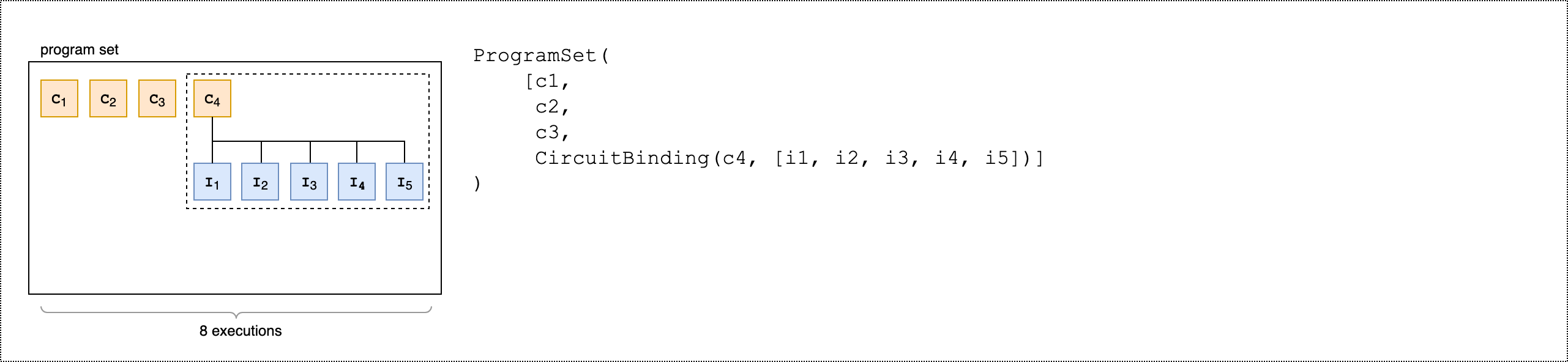
from braket.aws import AwsDevice
from braket.circuits import Circuit, FreeParameter
from braket.program_sets.circuit_binding import CircuitBinding
from braket.program_sets import ProgramSet

# Initialize the quantum device
device = AwsDevice("arn:aws:braket:eu-north-1::device/qpu/iqm/Garnet")

# Define circuits
circ1 = Circuit().h(0).cnot(0, 1)
circ2 = Circuit().rx(0, 0.785).ry(1, 0.393).cnot(1, 0)
circ3 = Circuit().t(0).t(1).cz(0, 1).s(0).cz(1, 2).s(1).s(2)
parameterize_circuit = Circuit().rx(0, FreeParameter("alpha")).cnot(0, 1).ry(1, FreeParameter("beta"))

# Create circuit bindings with different parameters
circuit_binding = CircuitBinding(
    circuit=parameterize_circuit,
    input_sets={
            'alpha': (0.10, 0.11, 0.22, 0.34, 0.45),
            'beta': (1.01, 1.01, 1.03, 1.04, 1.04),
    })

# Creating the program set
program_set_1 = ProgramSet([
    circ1,
    circ2,
    circ3,
    circuit_binding,
])
이 프로그램 세트에는 circ1, circ2, 및 circ3라는 네 가지 고유한 프로그램이 포함되어 있습니다circuit_binding. circuit_binding 프로그램은 5개의 서로 다른 파라미터 바인딩으로 실행되어 5개의 실행 파일을 생성합니다. 다른 세 개의 파라미터가 없는 프로그램은 각각 하나의 실행 파일을 생성합니다. 그러면 다음 이미지와 같이 총 8개의 실행 파일이 생성됩니다.
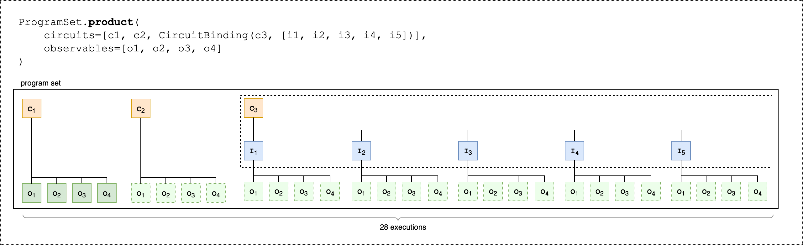
다음 두 번째 코드 예제에서는 product() 메서드를 사용하여 프로그램 세트의 각 실행 파일에 동일한 관찰 파일 세트를 연결하는 방법을 보여줍니다.
from braket.circuits.observables import I, X, Y, Z

observables = [Z(0) @ Z(1), X(0) @ X(1), Z(0) @ X(1), X(0) @ Z(1)]

program_set_2 = ProgramSet.product(
    circuits=[circ1, circ2, circuit_binding],
    observables=observables
)
파라미터가 없는 프로그램의 경우 관찰 가능한 각는 각 회로에 대해 측정됩니다. 파라미터 프로그램의 경우 다음 이미지와 같이 각 관찰 가능한는 각 입력 세트에 대해 측정됩니다.
다음 세 번째 코드 예제에서는 zip() 메서드를 사용하여 개별 관찰 항목을의 특정 파라미터 세트와 페어링하는 방법을 보여줍니다ProgramSet.
program_set_3 = ProgramSet.zip(
    circuits=circuit_binding,
    observables=observables + [Y(0) @ Y(1)]
)
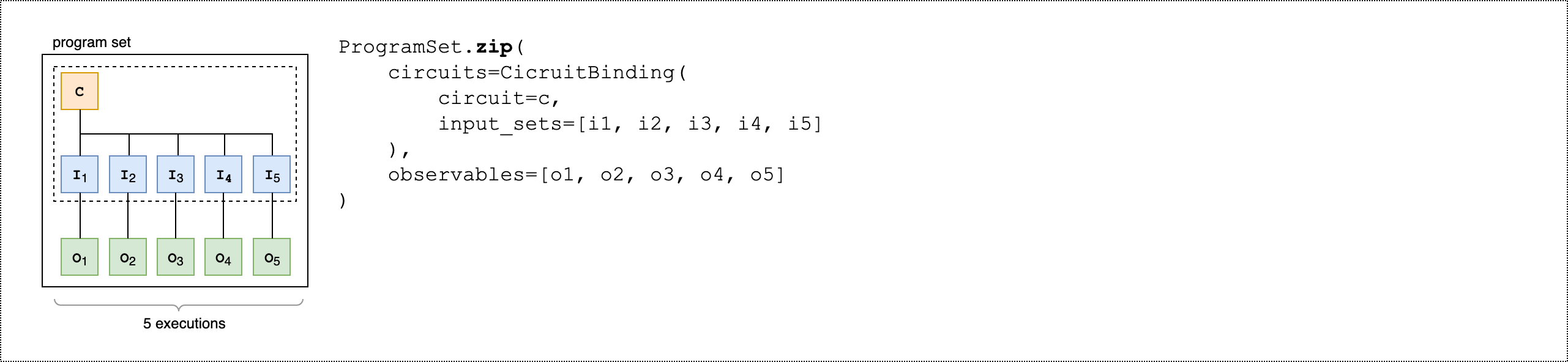
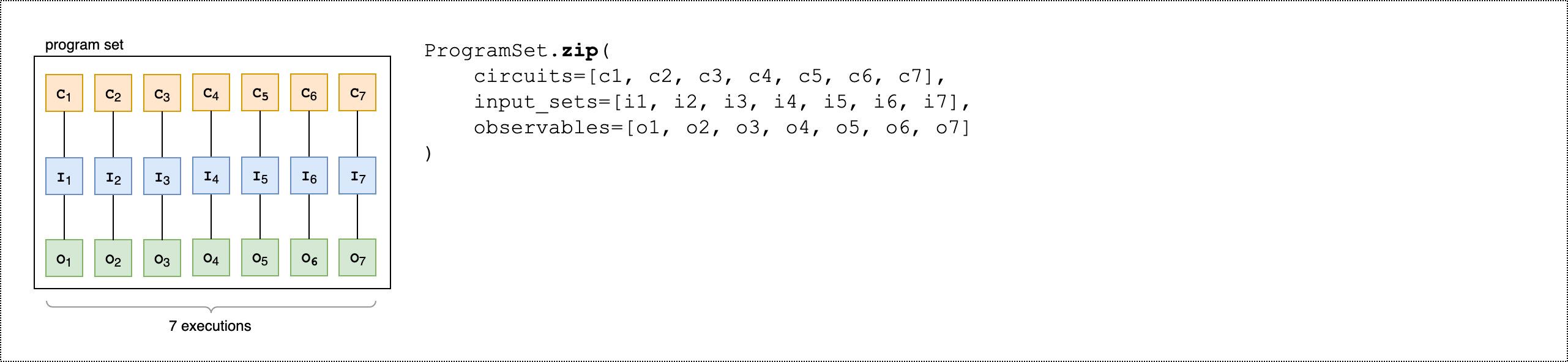
대신 관찰 가능한 목록을 회로 및 입력 세트 목록과 직접 압축CircuitBinding()할 수 있습니다.
program_set_4 = ProgramSet.zip(
    circuits=[circ1, circ2, circ3],
    input_sets=[{}, {}, {}],
    observables=observables[:3]
)
프로그램 세트에 대한 자세한 내용과 예제는 amazon-braket-examples Github의 프로그램 세트 폴더를
디바이스에서 프로그램 세트 검사 및 실행
프로그램 세트의 실행 파일 수는 고유한 파라미터 바인딩 회로 수와 같습니다. 다음 코드 예제를 사용하여 회로 실행 파일 및 샷의 총 수를 계산합니다.
# Number of shots per executable
shots = 10
num_executables = program_set_1.total_executables

# Calculate total number of shots across all executables
total_num_shots = shots*num_executables
참고
프로그램 세트를 사용하면 프로그램 세트의 모든 회로에서 총 샷 수를 기준으로 단일 작업당 요금과 샷당 요금을 지불합니다.
프로그램 세트를 실행하려면 다음 코드 예제를 사용합니다.
# Run the program set
task = device.run(
   program_set_1, shots=total_num_shots,
)
Rigetti 디바이스를 사용하는 경우 작업이 부분적으로 완료되고 부분적으로 대기열에 있는 동안 프로그램 세트가 RUNNING 상태로 유지될 수 있습니다. 더 빠른 결과를 얻으려면 프로그램 세트를 하이브리드 작업으로 제출하는 것이 좋습니다.
결과 분석
다음 코드를 실행하여에서 실행 파일의 결과를 분석하고 측정합니다ProgramSet.
# Get the results from a program set
result = task.result()

# Get the first executbable
first_program = result[0]
first_executable = first_program[0]

# Inspect the results of the first executable
measurements_from_first_executable = first_executable.measurements
print(measurements_from_first_executable)
부분 측정
양자 회로에서 모든 쿼비트를 측정하는 대신 부분 측정을 사용하여 개별 쿼비트 또는 쿼비트 하위 집합을 측정합니다.
참고
중간 회로 측정 및 피드 포워드 작업과 같은 추가 기능은 실험 기능으로 사용할 수 있습니다. IQM 디바이스의 동적 회로 액세스를 참조하세요.
예: 쿼비트의 하위 집합 측정
다음 코드 예제는 Bell 상태 회로에서 쿼비트 0만 측정하여 부분 측정을 보여줍니다.
from braket.devices import LocalSimulator
from braket.circuits import Circuit

# Use the local state vector simulator
device = LocalSimulator()

# Define an example bell circuit and measure qubit 0
circuit = Circuit().h(0).cnot(0, 1).measure(0)

# Run the circuit
task = device.run(circuit, shots=10)

# Get the results
result = task.result()

# Print the circuit and measured qubits
print(circuit)
print()
print("Measured qubits: ", result.measured_qubits)
수동 qubit 할당
의 양자 컴퓨터에서 양자 회로를 실행할 때 선택적으로 수동 qubit 할당을 사용하여 알고리즘에 사용되는 qubits를 제어할 Rigetti수 있습니다. Amazon Braket 콘솔
수동 qubit 할당을 사용하면 보다 정확하게 회로를 실행하고 개별 qubit 속성을 조사할 수 있습니다. 연구원과 고급 사용자는 최신 디바이스 보정 데이터를 기반으로 회로 설계를 최적화하여 더 정확한 결과를 얻을 수 있습니다.
다음 예제에서는 qubits 명시적으로를 할당하는 방법을 보여줍니다.
# Import the device module
from braket.aws import AwsDevice

device = AwsDevice("arn:aws:braket:us-west-1::device/qpu/rigetti/Ankaa-3")
circ = Circuit().h(0).cnot(0, 7)  # Indices of actual qubits in the QPU

# Set up S3 bucket (where results are stored)
my_bucket = "amazon-braket-s3-demo-bucket" # The name of the bucket
my_prefix = "your-folder-name" # The name of the folder in the bucket
s3_location = (my_bucket, my_prefix)

my_task = device.run(circ, s3_location, shots=100, disable_qubit_rewiring=True)
자세한 내용은 GitHub의 Amazon Braket 예제
축어 컴파일
게이트 기반 양자 컴퓨터에서 양자 회로를 실행할 때 컴파일러가 수정 없이 정의된 대로 정확하게 회로를 실행하도록 지시할 수 있습니다. 축어적 컴파일을 사용하여 전체 회로를 지정된 대로 정확하게 보존하거나 특정 부분만 보존하도록 지정할 수 있습니다(Rigetti에서만 지원). 하드웨어 벤치마킹 또는 오류 완화 프로토콜을 위한 알고리즘을 개발할 때는 하드웨어에서 실행 중인 게이트 및 회로 레이아웃을 정확하게 지정할 수 있는 옵션이 필요합니다. 축어 컴파일을 사용하면 특정 최적화 단계를 꺼서 컴파일 프로세스를 직접 제어할 수 있으므로 회로가 설계된 대로 정확하게 실행됩니다.
축어적 컴파일은 Rigetti, IonQ및 IQM 디바이스에서 지원되며 네이티브 게이트를 사용해야 합니다. 축어적 컴파일을 사용하는 경우 디바이스의 토폴로지를 확인하여 연결된에서 게이트가 호출되고 회로qubits가 하드웨어에서 지원되는 네이티브 게이트를 사용하는지 확인하는 것이 좋습니다. 다음 예제에서는 디바이스에서 지원하는 네이티브 게이트 목록에 프로그래밍 방식으로 액세스하는 방법을 보여줍니다.
device.properties.paradigm.nativeGateSet
의 경우 축어 컴파일과 함께 사용하도록 disableQubitRewiring=True를 설정하여 Rigetti qubit 재배선 기능을 꺼야 합니다. 컴파일에서 축약 상자를 사용할 때가 disableQubitRewiring=False 설정된 경우 양자 회로는 검증에 실패하고 실행되지 않습니다.
회로에 대해 축어적 컴파일이 활성화되어 있고 이를 지원하지 않는 QPU에서 실행되는 경우 지원되지 않는 작업으로 인해 작업이 실패했음을 나타내는 오류가 생성됩니다. 더 많은 양자 하드웨어가 기본적으로 컴파일러 함수를 지원하므로이 기능은 이러한 디바이스를 포함하도록 확장됩니다. 축어 컴파일을 지원하는 디바이스에는 다음 코드로 쿼리할 때 지원되는 작업으로 포함됩니다.
from braket.aws import AwsDevice
from braket.device_schema.device_action_properties import DeviceActionType
device = AwsDevice("arn:aws:braket:us-west-1::device/qpu/rigetti/Ankaa-3")
device.properties.action[DeviceActionType.OPENQASM].supportedPragmas
축어 컴파일 사용과 관련된 추가 비용은 없습니다. Amazon Braket 요금 페이지에 지정된 현재 요금을 기준으로 Amazon Braket
참고
OpenQASM을 사용하여 IonQ 디바이스에 대한 회로를 쓰고 회로를 물리적 쿼비트에 직접 매핑하려는 경우 OpenQASM에서 disableQubitRewiring 플래그를 완전히 무시#pragma braket verbatim하므로를 사용해야 합니다.
노이즈 시뮬레이션
로컬 노이즈 시뮬레이터를 인스턴스화하려면 다음과 같이 백엔드를 변경할 수 있습니다.
# Import the device module
from braket.aws import AwsDevice

device = LocalSimulator(backend="braket_dm")
두 가지 방법으로 노이즈가 많은 회로를 구축할 수 있습니다.
-
노이즈가 많은 회로를 아래에서 위로 빌드합니다.
-
기존의 노이즈 없는 회로를 만들고 전체적으로 노이즈를 주입합니다.
다음 예제에서는 탈분극 노이즈가 있는 기본 회로와 사용자 지정 Kraus 채널을 사용하는 접근 방식을 보여줍니다.
import scipy.stats
import numpy as np

# Bottom up approach
# Apply depolarizing noise to qubit 0 with probability of 0.1
circ = Circuit().x(0).x(1).depolarizing(0, probability=0.1)

# Create an arbitrary 2-qubit Kraus channel
E0 = scipy.stats.unitary_group.rvs(4) * np.sqrt(0.8)
E1 = scipy.stats.unitary_group.rvs(4) * np.sqrt(0.2)
K = [E0, E1]

# Apply a two-qubit Kraus channel to qubits 0 and 2
circ = circ.kraus([0, 2], K)
from braket.circuits import Noise

# Inject noise approach
# Define phase damping noise
noise = Noise.PhaseDamping(gamma=0.1)
# The noise channel is applied to all the X gates in the circuit
circ = Circuit().x(0).y(1).cnot(0, 2).x(1).z(2)
circ_noise = circ.copy()
circ_noise.apply_gate_noise(noise, target_gates=Gate.X)
다음 두 예제와 같이 회로 실행은 이전과 동일한 사용자 환경입니다.
예시 1
task = device.run(circ, shots=100)
Or
예시 2
task = device.run(circ_noise, shots=100)
추가 예제는 Braket 입문 노이즈 시뮬레이터 예제를 참조하세요.
