Multi zone architecture with an internet gateway using AWS Network Firewall
This topic provides a high-level view of a simple two zone VPC configuration using an internet gateway and AWS Network Firewall. It describes the basic route table modifications that are required to use the Network Firewall firewall.
Two zone architecture with internet gateway and the Network Firewall firewall
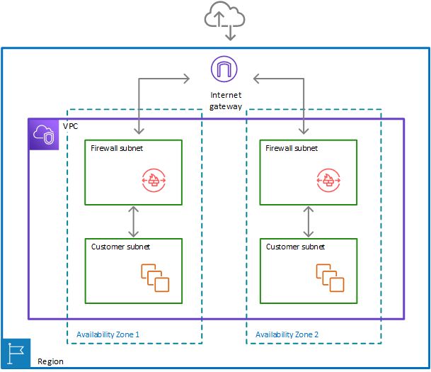
The following figure depicts a Network Firewall configuration for a VPC that spans multiple Availability Zones. In this case, each Availability Zone that the VPC spans has a firewall subnet and a customer subnet. The VPC has an internet gateway for internet access. All incoming traffic for the VPC routes to the firewall in the same Availability Zone as the destination customer subnet. All outgoing traffic routes through the firewalls.
Route tables in the two zone architecture with the firewall
The following figure depicts a VPC configuration with two Availability Zones. Each zone has its own Network Firewall firewall, which provides monitoring and protection for the subnets in the zone. You can expand this configuration to any number of zones in your VPC.
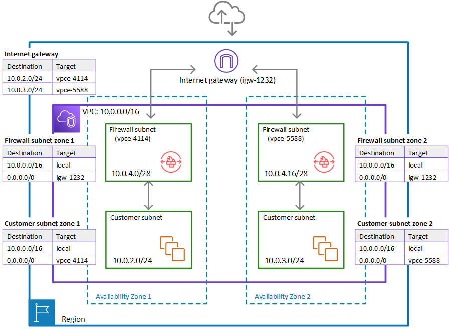
In the preceding figure, the route tables enforce similar traffic flows to the single Availability Zone model, with the primary difference being the splitting of incoming traffic by the internet gateway, to accommodate the two different customer subnets:
-
Internet gateway route table – Routes traffic that's destined for each customer subnet (range
10.0.2.0/24or10.0.3.0/24) to the firewall subnet in the same Availability Zone (vpce-4114orvpce-5588, respectively). -
Firewall subnet route tables – Route traffic that's destined for anywhere inside the VPC (
10.0.0.0/16) to the local address. Route traffic that's destined for anywhere else (0.0.0.0/0) to the internet gateway (igw-1232). These are identical to the route table for the firewall subnet in the single Availability Zone. -
Customer subnet route tables – Route traffic that's destined for anywhere inside the VPC (
10.0.0.0/16) to the local address. Route traffic that's destined for anywhere else (0.0.0.0/0) to the firewall subnet in the same Availability Zone (vpce-4114for zone AZ1 andvpce-5588for zone AZ2).
