Result of this procedure
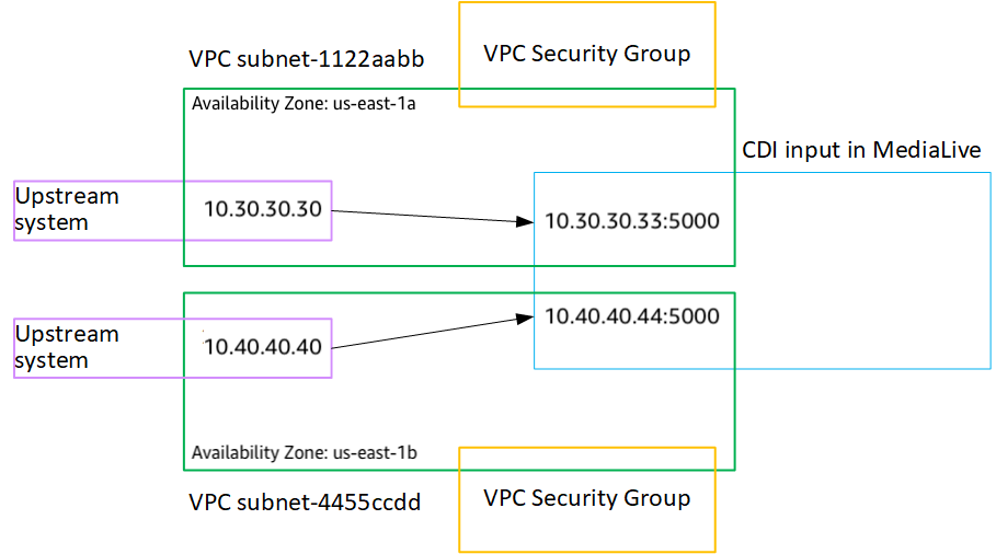
The results of this setup are illustrated in the diagram that follows. There are three main components:
-
The upstream system (purple boxes).
-
The VPC, with subnets (green boxes), and VPC security groups (yellow boxes).
-
The CDI input (blue box).
The CDI input has one or two endpoint URLs (the addresses in the blue box). These endpoints are elastic network interfaces (ENIs) on your VPC. MediaLive has permission to use these ENIs for its inputs. MediaLive has permission (through the IAM trusted entity role) to automatically manage the ENIs for its inputs.
The upstream system has two outputs. Each output has an IP address in one of the specified subnets in your VPC. The upstream system has permission (through the rules in one or more Amazon VPC security groups) to push content to these endpoints. The upstream system pushes the source content to both endpoints (if you are setting up a standard channel) or to one endpoint (if you are setting up a single-pipeline channel).
The upstream system has IP addresses in the VPC subnets, and the CDI input has endpoints in the same VPC subnets. In this way, the delivery of the content from the upstream system to MediaLive takes place within the security of the VPC.
The two IP addresses on the CDI input are fixed for the lifetime of the input. They are fixed, regardless of changes such as modifying other information in the input, or attaching the input to a different channel.
Keep in mind that with a push input, the upstream system must be pushing the video source to the input when you start the channel. The upstream system does not need to be pushing before then.
At runtime of the channel, MediaLive reacts to the content that is being pushed and ingests it.