Load balancer subnets and routing
Let's start with an illustration of how traffic flows when you configure an Application Load Balancer that faces the internet, to Amazon Elastic Compute Cloud (Amazon EC2) instances in a private subnet. This architecture reflects best practices when deploying an Application Load Balancer that’s open to the internet.
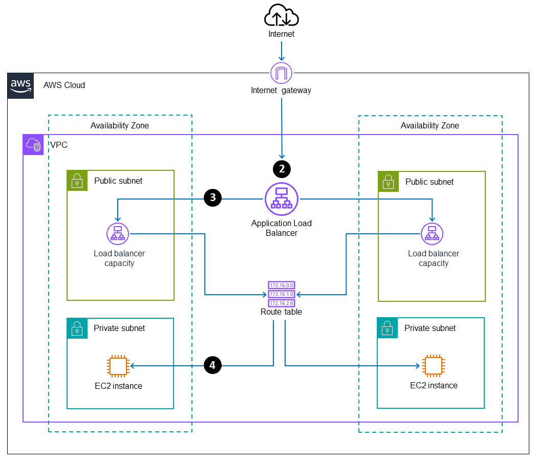
Inbound traffic path
The following diagram illustrates the virtual private cloud (VPC) subnets and routing associated with the incoming traffic flow, with the return traffic removed from the diagram for clarity.
-
Traffic from the internet flows in to the Application Load Balancer DNS name.
-
The Application Load Balancer is associated with two public subnets in the scenario that’s illustrated. The Elastic Load Balancing service creates load balancer capacity in each enabled Availability Zone, and sends traffic through the Availability Zone to determine the appropriate routing logic. The Application Load Balancer uses its internal logic to determine which target group and instance to route the traffic to.
-
The Application Load Balancer routes the request to the EC2 instance through a node that’s associated with the public subnet in the same Availability Zone. (These nodes are configured, managed, and scaled by the Elastic Load Balancing service and aren't visible to users.)
-
The route table routes the traffic locally within the VPC, between the public subnet and the private subnet, and to the EC2 instance.
Return traffic path
The following diagram illustrates the VPC subnets and routing associated with the traffic path back out to the internet, with the incoming traffic removed from the diagram for clarity.

-
The EC2 instance in the private subnet routes the outbound traffic through the route table.
-
The route table has a local route to the public subnet. It reaches the Application Load Balancer capacity that the traffic entered on, in the corresponding public subnet, by following the path back the way the traffic entered.
-
The Application Load Balancer routes traffic out through its public interface.
-
The public subnet's route table has a default route pointing to an internet gateway, which routes the traffic back out to the internet.
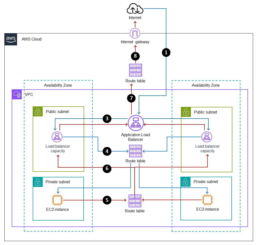
Complete traffic flow diagram
The following diagram combines the inbound and return traffic flows to provide a complete illustration of load balancer routing.
-
Traffic from the internet flows in to the Application Load Balancer DNS name.
-
The Application Load Balancer is associated with two public subnets in the scenario that’s illustrated. The Elastic Load Balancing service creates load balancer capacity in each enabled Availability Zone, and sends traffic through the Availability Zone to determine the appropriate routing logic. The Application Load Balancer uses its internal logic to determine which target group and instance to route the traffic to.
-
The Application Load Balancer routes the request to the EC2 instance through a node that’s associated with the public subnet in the same Availability Zone. (These nodes are configured, managed, and scaled by the Elastic Load Balancing service and aren't visible to users.)
-
The route table routes the traffic locally within the VPC, between the public subnet and the private subnet, and to the EC2 instance.
-
The EC2 instance in the private subnet routes the outbound traffic through the route table.
-
The route table has a local route to the public subnet. It reaches the Application Load Balancer capacity that the traffic entered on, in the corresponding public subnet, by following the path back the way the traffic entered.
-
The Application Load Balancer routes traffic out through its public interface.
-
The public subnet's route table has a default route pointing to an internet gateway, which routes the traffic back out to the internet.
