Example customer gateway device
configurations for dynamic routing (BGP)
Example configuration files
To download a sample configuration file with values specific to your Site-to-Site VPN
connection configuration, use the Amazon VPC console, the AWS command line or the Amazon EC2 API. For more
information, see Step 6: Download the configuration file.
You can also download generic example configuration files for dynamic
routing that do not include values specific to your Site-to-Site VPN connection
configuration: dynamic-routing-examples.zip
The files use placeholder values for some components. For example, they use:
-
Example values for the VPN connection ID, customer gateway ID and virtual
private gateway ID
-
Placeholders for the remote (outside) IP address AWS endpoints
(AWS_ENDPOINT_1
and
AWS_ENDPOINT_2
)
-
A placeholder for the IP address for the internet-routable external interface
on the customer gateway device
(your-cgw-ip-address
)
-
A placeholder for the pre-shared key value (pre-shared-key)
-
Example values for the tunnel inside IP addresses.
-
Example values for MTU setting.
In addition to providing placeholder values, the files specify the minimum
requirements for a Site-to-Site VPN connection of AES128, SHA1, and Diffie-Hellman group 2 in most
AWS Regions, and AES128, SHA2, and Diffie-Hellman group 14 in the AWS GovCloud
Regions. They also specify pre-shared keys for authentication. You must modify
the example configuration file to take advantage of additional security algorithms,
Diffie-Hellman groups, private certificates, and IPv6 traffic.
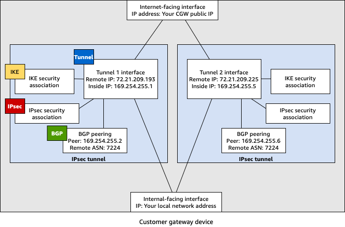
The following diagram provides an overview of the different components that are
configured on the customer gateway device. It includes example values for the tunnel
interface IP addresses.
User interface procedures for dynamic
routing
The following are some
example procedures for configuring a customer gateway device using its user interface
(if available).
- Check Point
-
The following are steps for configuring a Check Point Security Gateway
device running R77.10 or above, using the Gaia web portal and Check Point
SmartDashboard. You can also refer to the Amazon Web Services (AWS) VPN BGP article on the Check Point
Support Center.
To configure the tunnel interface
The first step is to create the VPN tunnels and provide the private
(inside) IP addresses of the customer gateway and virtual private
gateway for each tunnel. To create the first tunnel, use the information
provided under the IPSec Tunnel #1
section of the
configuration file. To create the second tunnel, use the values provided
in the IPSec Tunnel #2
section of the configuration file.
-
Connect to your security gateway over SSH. If you're using the
non-default shell, change to clish by running the following command:
clish
-
Set the customer gateway ASN (the ASN that was provided when the
customer gateway was created in AWS) by running the following
command.
set as 65000
-
Create the tunnel interface for the first tunnel, using the
information provided under the IPSec Tunnel #1
section
of the configuration file. Provide a unique name for your tunnel,
such as AWS_VPC_Tunnel_1
.
add vpn tunnel 1 type numbered local 169.254.44.234
remote 169.254.44.233
peer AWS_VPC_Tunnel_1
set interface vpnt1 state on
set interface vpnt1 mtu 1436
-
Repeat these commands to create the second tunnel, using the
information provided under the IPSec Tunnel #2
section
of the configuration file. Provide a unique name for your tunnel,
such as AWS_VPC_Tunnel_2
.
add vpn tunnel 1 type numbered local 169.254.44.38
remote 169.254.44.37
peer AWS_VPC_Tunnel_2
set interface vpnt2 state on
set interface vpnt2 mtu 1436
-
Set the virtual private gateway ASN.
set bgp external remote-as 7224
on
-
Configure the BGP for the first tunnel, using the information
provided IPSec Tunnel #1
section of the configuration
file.
set bgp external remote-as 7224
peer 169.254.44.233
on
set bgp external remote-as 7224
peer 169.254.44.233
holdtime 30
set bgp external remote-as 7224
peer 169.254.44.233
keepalive 10
-
Configure the BGP for the second tunnel, using the information
provided IPSec Tunnel #2
section of the configuration
file.
set bgp external remote-as 7224
peer 169.254.44.37
on
set bgp external remote-as 7224
peer 169.254.44.37
holdtime 30
set bgp external remote-as 7224
peer 169.254.44.37
keepalive 10
-
Save the configuration.
save config
To create a BGP policy
Next, create a BGP policy that allows the import of routes that are
advertised by AWS. Then, configure your customer gateway to advertise
its local routes to AWS.
-
In the Gaia WebUI, choose Advanced Routing,
Inbound Route Filters. Choose
Add, and select Add BGP Policy
(Based on AS).
-
For Add BGP Policy, select a value between
512 and 1024 in the first field, and enter the virtual private
gateway ASN in the second field (for example,
7224
).
-
Choose Save.
To advertise local routes
The following steps are for distributing local interface routes. You
can also redistribute routes from different sources (for example, static
routes, or routes obtained through dynamic routing protocols). For more
information, see the Gaia Advanced Routing R77 Versions Administration
Guide.
-
In the Gaia WebUI, choose Advanced
Routing, Routing Redistribution.
Choose Add Redistribution From and then select
Interface.
-
For To Protocol, select the virtual private
gateway ASN (for example, 7224
).
-
For Interface, select an internal interface.
Choose Save.
To define a new network object
Next, create a network object for each VPN tunnel, specifying the
public (outside) IP addresses for the virtual private gateway. You later
add these network objects as satellite gateways for your VPN community.
You also need to create an empty group to act as a placeholder for the
VPN domain.
-
Open the Check Point SmartDashboard.
-
For Groups, open the context menu and choose
Groups, Simple Group.
You can use the same group for each network object.
-
For Network Objects, open the context
(right-click) menu and choose New,
Interoperable Device.
-
For Name, enter the name that you provided
for your tunnel in step 1, for example,
AWS_VPC_Tunnel_1
or
AWS_VPC_Tunnel_2
.
-
For IPv4 Address, enter the outside IP
address of the virtual private gateway provided in the configuration
file, for example, 54.84.169.196
. Save your settings
and close the dialog box.
-
In the left category pane, choose Topology.
-
In the VPN Domain section, choose
Manually defined, and then browse to and
select the empty simple group that you created in step 2. Choose
OK.
-
Repeat these steps to create a second network object, using the
information under the IPSec Tunnel #2
section of the
configuration file.
-
Go to your gateway network object, open your gateway or cluster
object, and choose Topology.
-
In the VPN Domain section, choose
Manually defined, and then browse to and
select the empty simple group that you created in step 2. Choose
OK.
You can keep any existing VPN domain that you've configured.
However, ensure that the hosts and networks that are used or
served by the new VPN connection are not declared in that VPN
domain, especially if the VPN domain is automatically
derived.
If you're using clusters, edit the topology and define the interfaces
as cluster interfaces. Use the IP addresses that are specified in the
configuration file.
To create and configure the VPN community, IKE, and IPsec
settings
Next, create a VPN community on your Check Point gateway, to which you
add the network objects (interoperable devices) for each tunnel. You
also configure the Internet Key Exchange (IKE) and IPsec
settings.
-
From your gateway properties, choose IPSec
VPN in the category pane.
-
Choose Communities, New,
Star Community.
-
Provide a name for your community (for example,
AWS_VPN_Star
), and then choose Center
Gateways in the category pane.
-
Choose Add, and add your gateway or cluster
to the list of participant gateways.
-
In the category pane, choose Satellite
Gateways, Add, and add the
interoperable devices that you created earlier
(AWS_VPC_Tunnel_1
and
AWS_VPC_Tunnel_2
) to the list of participant
gateways.
-
In the category pane, choose Encryption. In
the Encryption Method section, choose
IKEv1 for IPv4 and IKEv2 for IPv6. In the
Encryption Suite section, choose
Custom, Custom
Encryption.
You must select the IKEv1 for IPv4 and IKEv2 for
IPv6 option for IKEv1 functionality.
-
In the dialog box, configure the encryption properties as follows,
and then choose OK when you're done:
-
In the category pane, choose Tunnel
Management. Choose Set Permanent
Tunnels, On all tunnels in the
community. In the VPN Tunnel
Sharing section, choose One VPN tunnel per
Gateway pair.
-
In the category pane, expand Advanced
Settings, and choose Shared
Secret.
-
Select the peer name for the first tunnel, choose
Edit, and then enter the pre-shared key as
specified in the configuration file in the IPSec Tunnel
#1
section.
-
Select the peer name for the second tunnel, choose
Edit, and then enter the pre-shared key as
specified in the configuration file in the IPSec Tunnel
#2
section.
-
Still in the Advanced Settings category,
choose Advanced VPN Properties, configure the
properties as follows, and then choose OK when
you're done:
-
IKE (Phase 1):
-
IPsec (Phase 2):
-
Choose Use Perfect Forward
Secrecy
-
Use Diffie-Hellman group:
Group 2 (1024 bit)
-
Renegotiate IPsec security associations
every
3600
seconds
To create firewall rules
Next, configure a policy with firewall rules and directional match
rules that allow communication between the VPC and the local network.
You then install the policy on your gateway.
-
In the SmartDashboard, choose Global
Properties for your gateway. In the category pane,
expand VPN, and choose
Advanced.
-
Choose Enable VPN Directional Match in VPN
Column, and choose OK.
-
In the SmartDashboard, choose Firewall, and
create a policy with the following rules:
-
Open the context menu for the cell in the VPN column, and choose
Edit Cell.
-
In the VPN Match Conditions dialog box,
choose Match traffic in this direction only.
Create the following directional match rules by choosing
Add for each, and then choose
OK when you're done:
-
internal_clear
> VPN community (The VPN
star community that you created earlier, for example,
AWS_VPN_Star
)
-
VPN community > VPN community
-
VPN community > internal_clear
-
In the SmartDashboard, choose Policy,
Install.
-
In the dialog box, choose your gateway and choose
OK to install the policy.
To modify the tunnel_keepalive_method property
Your Check Point gateway can use Dead Peer Detection (DPD) to identify
when an IKE association is down. To configure DPD for a permanent
tunnel, the permanent tunnel must be configured in the AWS VPN
community.
By default, the tunnel_keepalive_method
property for a
VPN gateway is set to tunnel_test
. You must change the
value to dpd
. Each VPN gateway in the VPN community that
requires DPD monitoring must be configured with the
tunnel_keepalive_method
property, including any 3rd
party VPN gateway. You cannot configure different monitoring mechanisms
for the same gateway.
You can update the tunnel_keepalive_method
property using
the GuiDBedit tool.
-
Open the Check Point SmartDashboard, and choose Security
Management Server, Domain Management
Server.
-
Choose File, Database Revision
Control... and create a revision snapshot.
-
Close all SmartConsole windows, such as the SmartDashboard,
SmartView Tracker, and SmartView Monitor.
-
Start the GuiBDedit tool. For more information, see the Check Point Database Tool article on the Check Point
Support Center.
-
Choose Security Management Server,
Domain Management Server.
-
In the upper left pane, choose Table,
Network Objects,
network_objects.
-
In the upper right pane, select the relevant Security
Gateway, Cluster object.
-
Press CTRL+F, or use the Search menu to
search for the following:
tunnel_keepalive_method
.
-
In the lower pane, open the context menu for
tunnel_keepalive_method
, and select
Edit.... Choose dpd,
OK.
-
Repeat steps 7 through 9 for each gateway that's part of the AWS
VPN Community.
-
Choose File, Save
All.
-
Close the GuiDBedit tool.
-
Open the Check Point SmartDashboard, and choose Security
Management Server, Domain Management
Server.
-
Install the policy on the relevant Security
Gateway, Cluster object.
For more information, see the New VPN features in R77.10 article on the Check Point Support
Center.
To enable TCP MSS clamping
TCP MSS clamping reduces the maximum segment size of TCP packets to
prevent packet fragmentation.
-
Navigate to the following directory: C:\Program Files
(x86)\CheckPoint\SmartConsole\R77.10\PROGRAM\
.
-
Open the Check Point Database Tool by running the
GuiDBEdit.exe
file.
-
Choose Table, Global
Properties, properties.
-
For fw_clamp_tcp_mss
, choose
Edit. Change the value to true
and then choose OK.
To verify the tunnel status
You can verify the tunnel status by running the following command from
the command line tool in expert mode.
vpn tunnelutil
In the options that display, choose 1 to verify the
IKE associations and 2 to verify the IPsec
associations.
You can also use the Check Point Smart Tracker Log to verify that packets
over the connection are being encrypted. For example, the following log
indicates that a packet to the VPC was sent over tunnel 1 and was
encrypted.
- SonicWALL
-
You can configure a SonicWALL device using the SonicOS management
interface. For more information about configuring the tunnels, see User interface procedures for
static routing.
You cannot configure BGP for the device using the management interface. Instead, use
the command line instructions provided in the example configuration file, under
the section named BGP.
Additional information for Cisco
devices
Some Cisco ASAs only support Active/Standby mode. When you use these Cisco ASAs, you
can have only one active tunnel at a time. The other standby tunnel becomes active if
the first tunnel becomes unavailable. With this redundancy, you should always have
connectivity to your VPC through one of the tunnels.
Cisco ASAs from version 9.7.1 and later support Active/Active mode. When you use these
Cisco ASAs, you can have both tunnels active at the same time. With this redundancy, you
should always have connectivity to your VPC through one of the tunnels.
For Cisco devices, you must do the following:
-
Configure the outside interface.
-
Ensure that the Crypto ISAKMP Policy Sequence number is unique.
-
Ensure that the Crypto List Policy Sequence number is unique.
-
Ensure that the Crypto IPsec Transform Set and the Crypto ISAKMP Policy
Sequence are harmonious with any other IPsec tunnels that are configured on the
device.
-
Ensure that the SLA monitoring number is unique.
-
Configure all internal routing that moves traffic between the customer gateway
device and your local network.
Additional information for Juniper
devices
The following information applies to the example configuration files for Juniper
J-Series and SRX customer gateway devices.
-
The outside interface is referred to as
ge-0/0/0.0
.
-
The tunnel interface IDs are referred to as st0.1
and st0.2
.
-
Ensure that you identify the security zone for the uplink interface (the
configuration information uses the default 'untrust' zone).
-
Ensure that you identify the security zone for the inside interface (the
configuration information uses the default 'trust' zone).
Testing
For more information about testing your Site-to-Site VPN connection, see Test a Site-to-Site VPN connection.