Configure dynamic routing for an AWS Virtual Private Network customer gateway device
The following are some example procedures for configuring a customer gateway device using its user interface (if available).
- Check Point
-
The following are steps for configuring a Check Point Security Gateway device running R77.10 or above, using the Gaia web portal and Check Point SmartDashboard. You can also refer to the Amazon Web Services (AWS) VPN BGP
article on the Check Point Support Center. To configure the tunnel interface
The first step is to create the VPN tunnels and provide the private (inside) IP addresses of the customer gateway and virtual private gateway for each tunnel. To create the first tunnel, use the information provided under the
IPSec Tunnel #1section of the configuration file. To create the second tunnel, use the values provided in theIPSec Tunnel #2section of the configuration file.-
Connect to your security gateway over SSH. If you're using the non-default shell, change to clish by running the following command:
clish -
Set the customer gateway ASN (the ASN that was provided when the customer gateway was created in AWS) by running the following command.
set as65000 -
Create the tunnel interface for the first tunnel, using the information provided under the
IPSec Tunnel #1section of the configuration file. Provide a unique name for your tunnel, such asAWS_VPC_Tunnel_1.add vpn tunnel 1 type numbered local169.254.44.234remote169.254.44.233peerAWS_VPC_Tunnel_1set interface vpnt1 state on set interface vpnt1 mtu1436 -
Repeat these commands to create the second tunnel, using the information provided under the
IPSec Tunnel #2section of the configuration file. Provide a unique name for your tunnel, such asAWS_VPC_Tunnel_2.add vpn tunnel 1 type numbered local169.254.44.38remote169.254.44.37peerAWS_VPC_Tunnel_2set interface vpnt2 state on set interface vpnt2 mtu1436 -
Set the virtual private gateway ASN.
set bgp external remote-as7224on -
Configure the BGP for the first tunnel, using the information provided
IPSec Tunnel #1section of the configuration file.set bgp external remote-as7224peer169.254.44.233on set bgp external remote-as7224peer169.254.44.233holdtime 30 set bgp external remote-as7224peer169.254.44.233keepalive 10 -
Configure the BGP for the second tunnel, using the information provided
IPSec Tunnel #2section of the configuration file.set bgp external remote-as7224peer169.254.44.37on set bgp external remote-as7224peer169.254.44.37holdtime 30 set bgp external remote-as7224peer169.254.44.37keepalive 10 -
Save the configuration.
save config
To create a BGP policy
Next, create a BGP policy that allows the import of routes that are advertised by AWS. Then, configure your customer gateway to advertise its local routes to AWS.
-
In the Gaia WebUI, choose Advanced Routing, Inbound Route Filters. Choose Add, and select Add BGP Policy (Based on AS).
-
For Add BGP Policy, select a value between 512 and 1024 in the first field, and enter the virtual private gateway ASN in the second field (for example,
7224). -
Choose Save.
To advertise local routes
The following steps are for distributing local interface routes. You can also redistribute routes from different sources (for example, static routes, or routes obtained through dynamic routing protocols). For more information, see the Gaia Advanced Routing R77 Versions Administration Guide
. -
In the Gaia WebUI, choose Advanced Routing, Routing Redistribution. Choose Add Redistribution From and then select Interface.
-
For To Protocol, select the virtual private gateway ASN (for example,
7224). -
For Interface, select an internal interface. Choose Save.
To define a new network object
Next, create a network object for each VPN tunnel, specifying the public (outside) IP addresses for the virtual private gateway. You later add these network objects as satellite gateways for your VPN community. You also need to create an empty group to act as a placeholder for the VPN domain.
-
Open the Check Point SmartDashboard.
-
For Groups, open the context menu and choose Groups, Simple Group. You can use the same group for each network object.
-
For Network Objects, open the context (right-click) menu and choose New, Interoperable Device.
-
For Name, enter the name that you provided for your tunnel in step 1, for example,
AWS_VPC_Tunnel_1orAWS_VPC_Tunnel_2. -
For IPv4 Address, enter the outside IP address of the virtual private gateway provided in the configuration file, for example,
54.84.169.196. Save your settings and close the dialog box.
-
In the left category pane, choose Topology.
-
In the VPN Domain section, choose Manually defined, and then browse to and select the empty simple group that you created in step 2. Choose OK.
-
Repeat these steps to create a second network object, using the information under the
IPSec Tunnel #2section of the configuration file. -
Go to your gateway network object, open your gateway or cluster object, and choose Topology.
-
In the VPN Domain section, choose Manually defined, and then browse to and select the empty simple group that you created in step 2. Choose OK.
Note
You can keep any existing VPN domain that you've configured. However, ensure that the hosts and networks that are used or served by the new VPN connection are not declared in that VPN domain, especially if the VPN domain is automatically derived.
Note
If you're using clusters, edit the topology and define the interfaces as cluster interfaces. Use the IP addresses that are specified in the configuration file.
To create and configure the VPN community, IKE, and IPsec settings
Next, create a VPN community on your Check Point gateway, to which you add the network objects (interoperable devices) for each tunnel. You also configure the Internet Key Exchange (IKE) and IPsec settings.
-
From your gateway properties, choose IPSec VPN in the category pane.
-
Choose Communities, New, Star Community.
-
Provide a name for your community (for example,
AWS_VPN_Star), and then choose Center Gateways in the category pane. -
Choose Add, and add your gateway or cluster to the list of participant gateways.
-
In the category pane, choose Satellite Gateways, Add, and add the interoperable devices that you created earlier (
AWS_VPC_Tunnel_1andAWS_VPC_Tunnel_2) to the list of participant gateways. -
In the category pane, choose Encryption. In the Encryption Method section, choose IKEv1 for IPv4 and IKEv2 for IPv6. In the Encryption Suite section, choose Custom, Custom Encryption.
Note
You must select the IKEv1 for IPv4 and IKEv2 for IPv6 option for IKEv1 functionality.
-
In the dialog box, configure the encryption properties as follows, and then choose OK when you're done:
-
IKE Security Association (Phase 1) Properties:
-
Perform key exchange encryption with: AES-128
-
Perform data integrity with: SHA-1
-
-
IPsec Security Association (Phase 2) Properties:
-
Perform IPsec data encryption with: AES-128
-
Perform data integrity with: SHA-1
-
-
-
In the category pane, choose Tunnel Management. Choose Set Permanent Tunnels, On all tunnels in the community. In the VPN Tunnel Sharing section, choose One VPN tunnel per Gateway pair.
-
In the category pane, expand Advanced Settings, and choose Shared Secret.
-
Select the peer name for the first tunnel, choose Edit, and then enter the pre-shared key as specified in the configuration file in the
IPSec Tunnel #1section. -
Select the peer name for the second tunnel, choose Edit, and then enter the pre-shared key as specified in the configuration file in the
IPSec Tunnel #2section.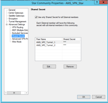
-
Still in the Advanced Settings category, choose Advanced VPN Properties, configure the properties as follows, and then choose OK when you're done:
-
IKE (Phase 1):
-
Use Diffie-Hellman group:
Group 2 (1024 bit) -
Renegotiate IKE security associations every
480minutes
-
-
IPsec (Phase 2):
-
Choose Use Perfect Forward Secrecy
-
Use Diffie-Hellman group:
Group 2 (1024 bit) -
Renegotiate IPsec security associations every
3600seconds
-
-
To create firewall rules
Next, configure a policy with firewall rules and directional match rules that allow communication between the VPC and the local network. You then install the policy on your gateway.
-
In the SmartDashboard, choose Global Properties for your gateway. In the category pane, expand VPN, and choose Advanced.
-
Choose Enable VPN Directional Match in VPN Column, and choose OK.
-
In the SmartDashboard, choose Firewall, and create a policy with the following rules:
-
Allow the VPC subnet to communicate with the local network over the required protocols.
-
Allow the local network to communicate with the VPC subnet over the required protocols.
-
-
Open the context menu for the cell in the VPN column, and choose Edit Cell.
-
In the VPN Match Conditions dialog box, choose Match traffic in this direction only. Create the following directional match rules by choosing Add for each, and then choose OK when you're done:
-
internal_clear> VPN community (The VPN star community that you created earlier, for example,AWS_VPN_Star) -
VPN community > VPN community
-
VPN community >
internal_clear
-
-
In the SmartDashboard, choose Policy, Install.
-
In the dialog box, choose your gateway and choose OK to install the policy.
To modify the tunnel_keepalive_method property
Your Check Point gateway can use Dead Peer Detection (DPD) to identify when an IKE association is down. To configure DPD for a permanent tunnel, the permanent tunnel must be configured in the AWS VPN community.
By default, the
tunnel_keepalive_methodproperty for a VPN gateway is set totunnel_test. You must change the value todpd. Each VPN gateway in the VPN community that requires DPD monitoring must be configured with thetunnel_keepalive_methodproperty, including any 3rd party VPN gateway. You cannot configure different monitoring mechanisms for the same gateway.You can update the
tunnel_keepalive_methodproperty using the GuiDBedit tool.-
Open the Check Point SmartDashboard, and choose Security Management Server, Domain Management Server.
-
Choose File, Database Revision Control... and create a revision snapshot.
-
Close all SmartConsole windows, such as the SmartDashboard, SmartView Tracker, and SmartView Monitor.
-
Start the GuiBDedit tool. For more information, see the Check Point Database Tool
article on the Check Point Support Center. -
Choose Security Management Server, Domain Management Server.
-
In the upper left pane, choose Table, Network Objects, network_objects.
-
In the upper right pane, select the relevant Security Gateway, Cluster object.
-
Press CTRL+F, or use the Search menu to search for the following:
tunnel_keepalive_method. -
In the lower pane, open the context menu for
tunnel_keepalive_method, and select Edit.... Choose dpd, OK. -
Repeat steps 7 through 9 for each gateway that's part of the AWS VPN Community.
-
Choose File, Save All.
-
Close the GuiDBedit tool.
-
Open the Check Point SmartDashboard, and choose Security Management Server, Domain Management Server.
-
Install the policy on the relevant Security Gateway, Cluster object.
For more information, see the New VPN features in R77.10
article on the Check Point Support Center. To enable TCP MSS clamping
TCP MSS clamping reduces the maximum segment size of TCP packets to prevent packet fragmentation.
-
Navigate to the following directory:
C:\Program Files
                                    (x86)\CheckPoint\SmartConsole\R77.10\PROGRAM\
. -
Open the Check Point Database Tool by running the
GuiDBEdit.exefile. -
Choose Table, Global Properties, properties.
-
For
fw_clamp_tcp_mss, choose Edit. Change the value totrueand then choose OK.
To verify the tunnel status
You can verify the tunnel status by running the following command from the command line tool in expert mode.
vpn tunnelutilIn the options that display, choose 1 to verify the IKE associations and 2 to verify the IPsec associations.
You can also use the Check Point Smart Tracker Log to verify that packets over the connection are being encrypted. For example, the following log indicates that a packet to the VPC was sent over tunnel 1 and was encrypted.
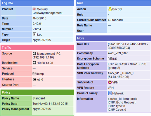
-
- SonicWALL
-
You can configure a SonicWALL device using the SonicOS management interface. For more information about configuring the tunnels, see Configure static routing for an AWS Site-to-Site VPN customer gateway device.
You cannot configure BGP for the device using the management interface. Instead, use the command line instructions provided in the example configuration file, under the section named BGP.
