1 Hardware
1.1 Block diagram
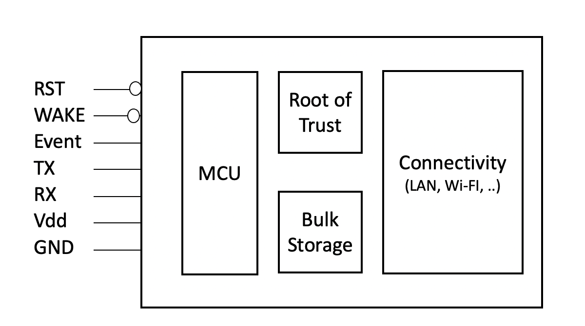
Figure 1 - Simplified block diagram
1.2 Pin definitions
1.2.1GND (input) – Ground-
1.2.2VCC (input) – 3.3v-
1.2.3TXD (output) – Serial interface Universal Asynchronous Receiver the Transmitter (UART) TX from module-
UART output to the host processor/application processor.
1.2.4RXD (input) – Serial interface Universal Asynchronous Receiver the Transmitter (UART) RX to module-
UART input to the ExpressLink, from the host processor/application processor.
1.2.5RST (input) – holds module in reset-
When asserted (low), the ExpressLink module is held in reset (low power, disconnected, all queues emptied and error conditions cleared).
1.2.6WAKE (input) – low-power sleep mode wakeup-
When not asserted (high), the ExpressLink module is allowed to enter a low power sleep mode. If in low power sleep mode and asserted (low), this will awake the ExpressLink module.
1.2.7Event (output) – Asynchronous Event Flag-
When asserted, the ExpressLink module indicates to the host processor that an event has occurred (disconnect error or message received on a subscribed topic) and a notification is available in the event queue waiting to be delivered. It is de-asserted when the event queue is emptied. A host processor can connect an interrupt input to this signal (rising edge) or can poll the event queue at regular intervals (see 7.2.1 EVENT? ⁞ Request the next event in the queue).
