Resiliency at the edge
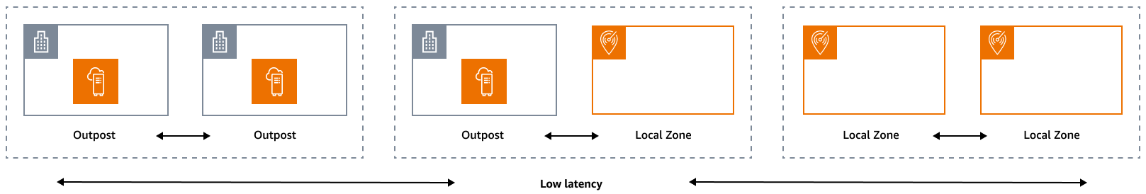
The reliability pillar encompasses the ability of a workload to perform its intended function correctly and consistently when it is expected to. This includes the ability to operate and test the workload through its lifecycle. In this sense, when you design a resilient architecture at the edge, you must first consider which infrastructures you will use to deploy that architecture. There are three possible combinations to implement by using AWS Local Zones and AWS Outposts: Outpost to Outpost, Outpost to Local Zone, and Local Zone to Local Zone, as illustrated in the following diagram. Although there are other possibilities for resilient architectures, such as combining AWS edge services with traditional on-premises infrastructure or AWS Regions, this guide focuses on these three combinations that apply to the design of hybrid cloud services
Infrastructure considerations
At AWS, one of the core principles of service design is to avoid single points of failure in the underlying physical infrastructure. Because of this principle, AWS software and systems use multiple Availability Zones and are resilient to the failure of a single zone. At the edge, AWS offers infrastructures that are based on Local Zones and Outposts. Therefore, a critical factor in ensuring resilience in infrastructure design is defining where an application's resources are deployed.
Local Zones
Local Zones act similarly to Availability Zones within their AWS Region, because they can be selected as a placement location for zonal AWS resources such as subnets and EC2 instances. However, they aren't located in an AWS Region, but near large population, industrial, and IT centers where no AWS Region exists today. Despite this, they still retain high-bandwidth, secure connections between local workloads in the Local Zone and workloads that are running in the AWS Region. Therefore, you should use Local Zones to deploy workloads closer to your users for low-latency requirements.
Outposts
AWS Outposts is a fully managed service that extends AWS infrastructure, AWS services, APIs, and tools to your data center. The same hardware infrastructure that's used in the AWS Cloud is installed in your data center. Outposts are then connected to the nearest AWS Region. You can use Outposts to support your workloads that have low latency or local data processing requirements.
Parent Availability Zones
Each Local Zone or Outpost has a parent Region (also referred to as home Region). The parent Region is where the control plane of the AWS edge infrastructure (Outpost or Local Zone) is anchored. In the case of Local Zones, the parent Region is a fundamental architectural component of a Local Zone and cannot be modified by customers. AWS Outposts extends the AWS Cloud to your on-premises environment, so you must select a specific Region and Availability Zone during the ordering process. This selection anchors the control plane of your Outposts deployment to the chosen AWS infrastructure.
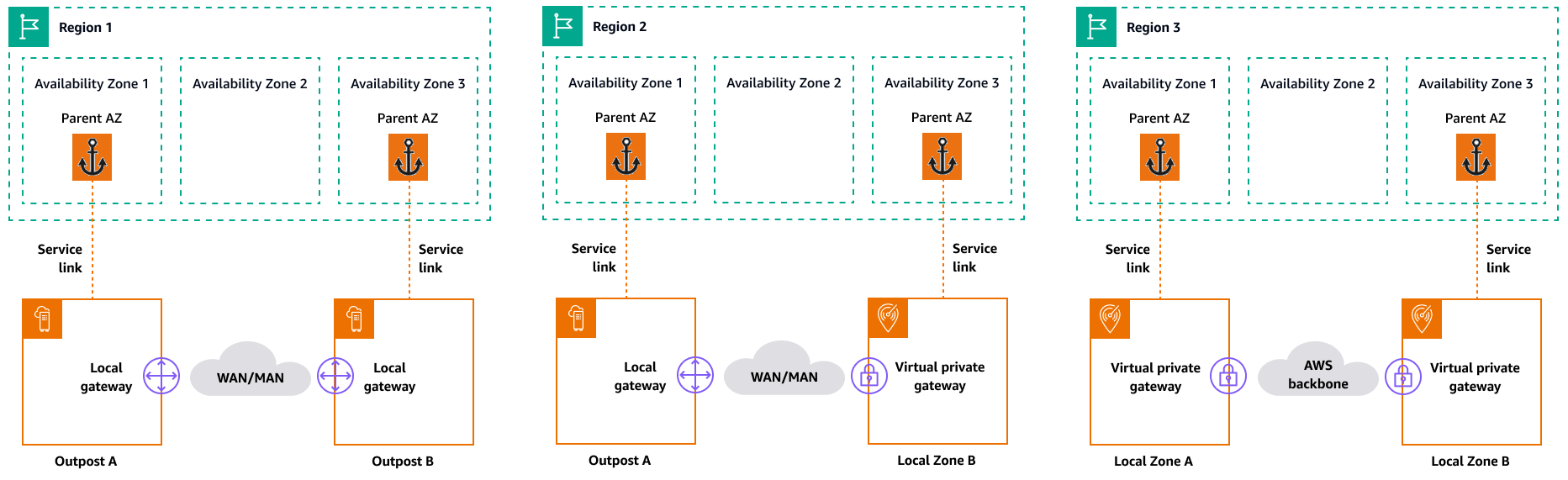
When you develop high availability architectures in the edge, the parent Region of these infrastructures, such as Outposts or Local Zones, must be the same, so that a VPC can be extended between them. This extended VPC is the basis for creating these high-availability architectures. When you define a highly resilient architecture, this is why you must validate the parent Region and the Availability Zone of the Region where the service will be (or is) anchored. As illustrated in the following diagram, if you want to deploy a high availability solution between two Outposts, you must choose two different Availability Zones to anchor the Outposts. This allows for a Multi-AZ architecture from a control plane perspective. If you want to deploy a highly available solution that includes one or more Local Zones, you must first validate the parent Availability Zone where the infrastructure is anchored. For this purpose, use the following AWS CLI command:
aws ec2 describe-availability-zones --zone-ids use1-mia1-az1
Output of the previous command:
{     "AvailabilityZones": [
          {
             "State": "available",
             "OptInStatus": "opted-in",
             "Messages": [],
             "RegionName": "us-east-1",
             "ZoneName": "us-east-1-mia-1a",
             "ZoneId": "use1-mia1-az1",
             "GroupName": "us-east-1-mia-1",
             "NetworkBorderGroup": "us-east-1-mia-1",
             "ZoneType": "local-zone",
             "ParentZoneName": "us-east-1d",
             "ParentZoneId": "use1-az2"
         }
     ]
 }
In this example, the Miami Local Zone (us-east-1d-mia-1a1) is anchored
in the us-east-1d-az2 Availability
Zone. Therefore, if you need to create a resilient architecture at the edge, you
must ensure that the secondary infrastructure (either Outposts or Local Zones) is
anchored to an Availability Zone other than us-east-1d-az2. For example, us-east-1d-az1 would be
valid.
The following diagram provides examples of highly available edge infrastructures.
Networking considerations
This section discusses initial considerations for networking at the edge, mainly for connections to access the edge infrastructure. It reviews valid architectures that provide a resilient network for the service link.
Resiliency networking for Local Zones
Local Zones are connected to the parent Region with multiple, redundant, secure,
high-speed links that enable you to consume any Regional service, such as Amazon S3 and
Amazon RDS, seamlessly. You are responsible for providing connectivity from your
on-premises environment or users to the Local Zone. Regardless of the connectivity
architecture you choose (for example, VPN or AWS Direct Connect), the latency that must be
achieved through the network links must be equivalent to avoid any impact on
application performance in the event of a failure in a main link. If you're using
AWS Direct Connect, the applicable resilience architectures are the same as those for
accessing an AWS Region, as documented in AWS Direct Connect resiliency
recommendations
Resiliency networking for Outposts
In contrast to Local Zones, Outposts have redundant connectivity for accessing workloads deployed in Outposts from your local network. This redundancy is achieved through two Outposts network devices (ONDs). Each OND requires at least two fiber connections at 1 Gbps, 10 Gbps, 40 Gbps, or 100 Gbps to your local network. These connections must be configured as a link aggregation group (LAG) to allow for the scalable addition of more links.
Uplink speed |
Number of uplinks |
|---|---|
1 Gbps |
1, 2, 4, 6, or 8 |
10 Gbps |
1, 2, 4, 8, 12, or 16 |
40 or 100 Gbps |
1, 2, or 4 |
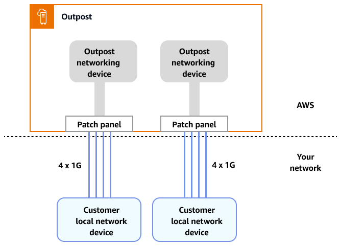
For more information about this connectivity, see Local network connectivity for Outposts Racks in the AWS Outposts documentation.
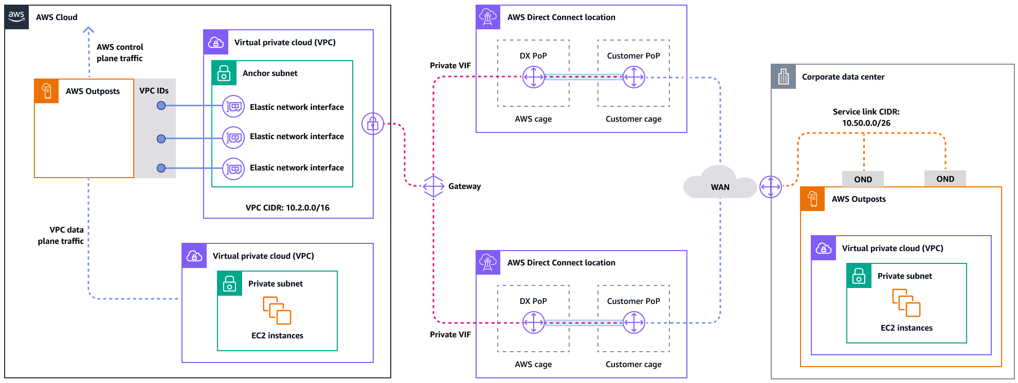
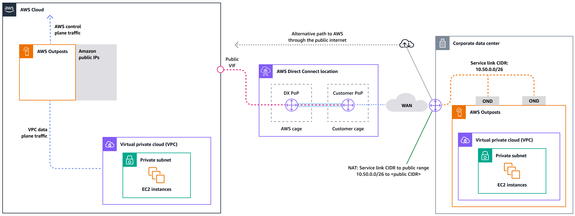
For an optimal experience and resiliency, AWSrecommends that you use redundant connectivity of at least 500 Mbps (1 Gbps is better) for the service link connection to the AWS Region. You can use AWS Direct Connect or an internet connection for the service link. This minimum enables you to launch EC2 instances, attach EBS volumes, and access AWS services, such as Amazon EKS, Amazon EMR, and CloudWatch metrics.
The following diagram illustrates this architecture for a highly available private connection.
The following diagram illustrates this architecture for a highly available public connection.
Scaling Outposts rack deployments with ACE racks
The Aggregation, Core, Edge (ACE) rack serves as a critical aggregation point for
AWS Outposts multi-rack deployments, and is primarily recommended for installations that
exceed three racks or for planning future expansion. Each ACE rack features four
routers that support 10 Gbps, 40 Gbps, and 100 Gbps connections (100 Gbps is
optimal). Each rack can connect to up to four upstream customer devices for maximum
redundancy. ACE racks consume up to 10 kVA of power and weigh up to 705 lbs. Key
benefits include reduced physical networking requirements, fewer fiber cabling
uplinks, and decreased VLAN virtual interfaces. AWS monitors these racks through
telemetry data via VPN tunnels and works closely with customers during installation
to ensure proper power availability, network configuration, and optimal placement.
The ACE rack architecture provides increasing value as deployments scale, and
effectively simplifies connectivity while reducing complexity and physical port
requirements in larger installations. For more information, see the AWS blog
post Scaling
AWS Outposts rack deployments with ACE Rack
Distributing instances across Outposts and Local Zones
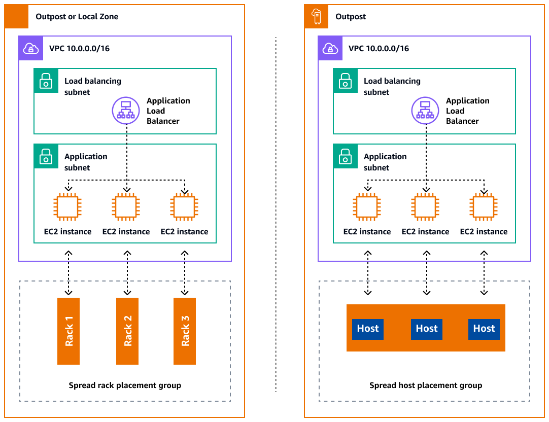
Outposts and Local Zones have a finite number of compute servers. If your application deploys multiple related instances, these instances might deploy on the same server or on servers in the same rack unless they are configured differently. In addition to the default options, you can distribute instances across servers to mitigate the risk of running related instances on the same infrastructure. You can also distribute instances across multiple racks by using partition placement groups. This is called the spread rack distribution model. Use automatic distribution to spread instances across partitions in the group, or deploy instances to selected target partitions. By deploying instances to target partitions, you can deploy selected resources to the same rack while distributing other resources across racks. Outposts also provides another option called spread host that lets you distribute your workload at the host level. The following diagram shows the spread rack and spread host distribution options.
Amazon RDS Multi-AZ in AWS Outposts
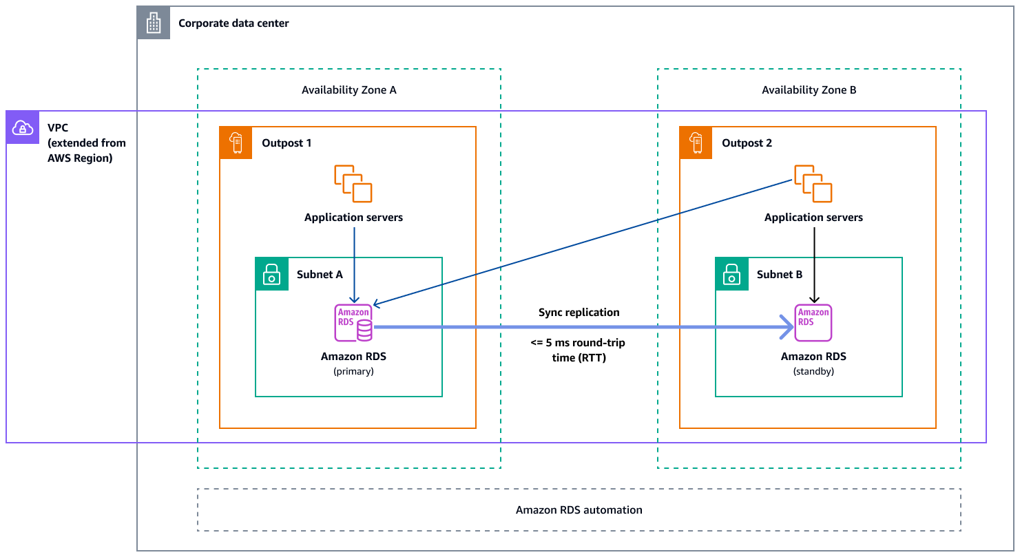
When you use Multi-AZ instance deployments on Outposts, Amazon RDS creates two database instances across two Outposts. Each Outpost runs on its own physical infrastructure and connects to different Availability Zones in a Region for high availability. When two Outposts are connected through a customer-managed local connection, Amazon RDS manages synchronous replication between the primary and standby database instances. In case of a software or infrastructure failure, Amazon RDS automatically promotes the standby instance to the primary role and updates the DNS record to point to the new primary instance. For Multi-AZ deployments, Amazon RDS creates a primary DB instance on one Outpost and synchronously replicates the data to a standby DB instance on a different Outpost. Multi-AZ deployments on Outposts operate like Multi-AZ deployments in AWS Regions, with the following differences:
-
They require a local connection between two or more Outposts.
-
They require customer-owned IP (CoIP) address pools. For more information, see Customer-owned IP addresses for Amazon RDS on AWS Outposts in the Amazon RDS documentation.
-
Replication runs on your local network.
Multi-AZ deployments are available for all supported versions of MySQL and PostgreSQL on Amazon RDS on Outposts. Local backups are not supported for Multi-AZ deployments.
The following diagram shows the architecture for Amazon RDS on Outposts Multi-AZ configurations.
Failover mechanisms
Load balancing and automatic scaling
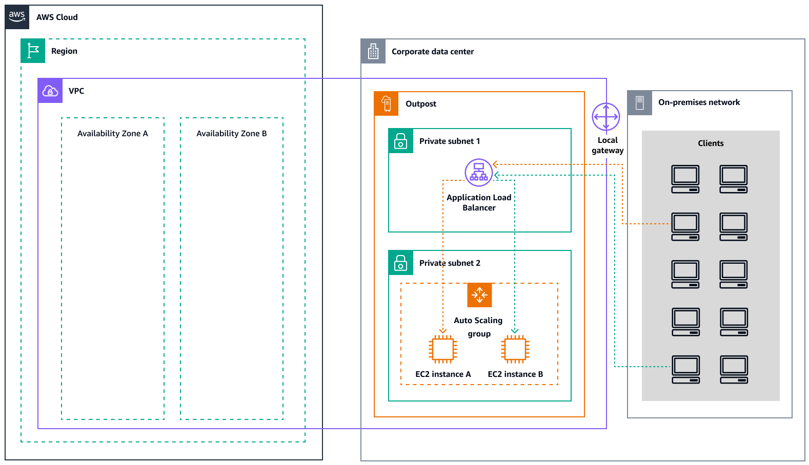
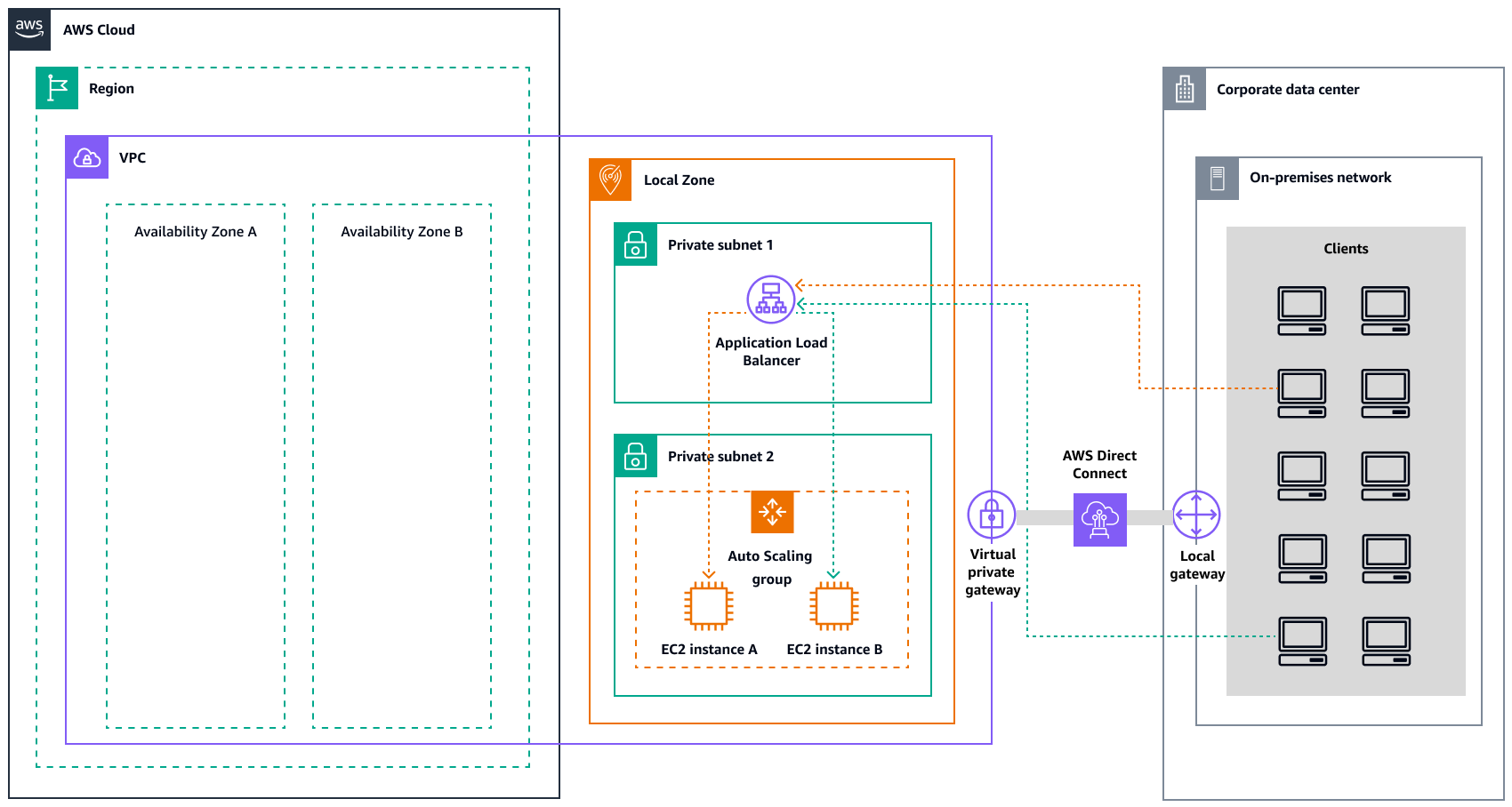
Elastic Load Balancing (ELB) automatically distributes your incoming application traffic across all the EC2 instances that you are running. ELB helps manage incoming requests by optimally routing traffic so that no single instance is overwhelmed. To use ELB with your Amazon EC2 Auto Scaling group, attach the load balancer to your Auto Scaling group. This registers the group with the load balancer, which acts as a single point of contact for all incoming web traffic to your group. When you use ELB with your Auto Scaling group, it is not necessary to register individual EC2 instances with the load balancer. Instances that are launched by your Auto Scaling group are automatically registered with the load balancer. Similarly, instances that are terminated by your Auto Scaling group are automatically deregistered from the load balancer. After you attach a load balancer to your Auto Scaling group, you can configure your group to use ELB metrics (such as the Application Load Balancer request count per target) to scale the number of instances in the group as demand fluctuates. Optionally, you can add ELB health checks to your Auto Scaling group so that Amazon EC2 Auto Scaling can identify and replace unhealthy instances based on these health checks. You can also create an Amazon CloudWatch alarm that notifies you if the healthy host count of the target group is lower than allowed.
The following diagram illustrates how an Application Load Balancer manages workloads on Amazon EC2 in AWS Outposts.
The following diagram illustrates a similar architecture for Amazon EC2 in Local Zones.
Note
Application Load Balancers are available in both AWS Outposts and Local Zones. However, to use an Application Load Balancer in
AWS Outposts, you need to size the Amazon EC2 capacity to provide the scalability that the
load balancer requires. For more information about sizing a load balancer in
AWS Outposts, see the AWS blog post Configuring an Application Load Balancer on AWS Outposts
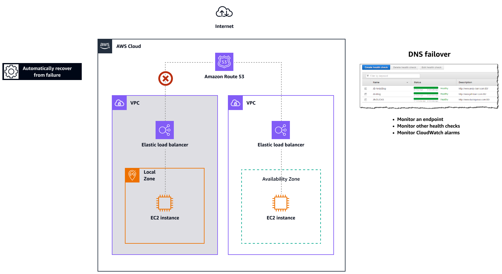
Amazon Route 53 for DNS failover
When you have more than one resource performing the same function—for
example, multiple HTTP or mail servers—you can configure Amazon Route 53example.com, is hosted on two
servers. One server is in a Local Zone and the other server is in an Outpost. You can
configure Route 53 to check the health of those servers and to respond to DNS queries
for example.com by using only the servers that are currently healthy.
If you're using alias records to route traffic to selected AWS resources, such as
ELB load balancers, you can configure Route 53 to evaluate the health of the resource
and route traffic only to resources that are healthy. When you configure an alias
record to evaluate the health of a resource, you don't need to create a health check
for that resource.
The following diagram illustrates Route 53 failover mechanisms.
Notes
-
If you're creating failover records in a private hosted zone, you can create a CloudWatch metric, associate an alarm with the metric, and then create a health check that is based on the data stream for the alarm.
-
To make an application publicly accessible in AWS Outposts by using an Application Load Balancer, set up networking configurations that enable Destination Network Address Translation (DNAT) from public IPs to the load balancer's fully qualified domain name (FQDN), and create a Route 53 failover rule with health checks that point to the exposed public IP. This combination ensures reliable public access to your Outposts-hosted application.
Amazon Route 53 Resolver on AWS Outposts
Amazon Route 53 Resolver is available on Outposts racks. It provides your on-premises services and applications with local DNS resolution directly from Outposts. Local Route 53 Resolver endpoints also enable DNS resolution between Outposts and your on-premises DNS server. Route 53 Resolver on Outposts helps improve the availability and performance of your on-premises applications.
One of the typical use cases for Outposts is to deploy applications that require low-latency access to on-premises systems, such as factory equipment, high-frequency trading applications, and medical diagnosis systems.
When you opt in to use local Route 53 Resolvers on Outposts, applications and services will continue to benefit from local DNS resolution to discover other services, even if connectivity to a parent AWS Region is lost. Local Resolvers also help reduce latency for DNS resolutions because query results are cached and served locally from the Outposts, which eliminates unnecessary round-trips to the parent AWS Region. All DNS resolutions for applications in Outposts VPCs that use private DNS are served locally.
In addition to enabling local Resolvers, this launch also enables local Resolver endpoints. Route 53 Resolver outbound endpoints enable Route 53 Resolvers to forward DNS queries to DNS resolvers that you manage―for example, on your on-premises network. In contrast, Route 53 Resolver inbound endpoints forward the DNS queries they receive from outside the VPC to the Resolver that's running on Outposts. It allows you to send DNS queries for services deployed on a private Outposts VPC from outside that VPC. For more information about inbound and outbound endpoints, see Resolving DNS queries between VPCs and your network in the Route 53 documentation.
