Using VMware VCDR and NetApp CVO for Disaster Recovery (DR)
Publication date: March 17, 2022 (Diagram history)
This architecture shows you how to bring Disaster-Recovery-as-a-Service (DRaaS) and the power of AWS to your on-premises VMware workloads.
Using VMware VCDR and NetApp CVO for DR Diagram

-
Deploy the VMware Cloud Disaster Recovery (VCDR) pilot light cluster in the VCDR portal. This pilot light cluster will serve as a minimum footprint in VMware Cloud on AWS (VMC) that will scale up in a disaster recovery (DR) event. Without this pilot light cluster, provisioning and configuring the VMC environment would take place after a disaster has been declared, but prior to failover. Note that this will add to the recovery time objective (RTO).
-
Deploy the VCDR DRaaS connector virtual appliance in the on-premises VMware environment. This virtual appliance provides a service connection into VCDR. Define your VM protection groups (groups of VMs with their respective snapshot schedules), the corresponding Recovery Point Objective (RPO), and the backup retention period. These are the DR policies that will be applied to the VMs in the on-premises vSphere environment.
-
The DRaaS connector replicates the VM data from the on-premises vSphere environment to the VCDR cloud-based services.
-
In a DR event, the replicated data in the scale-out file system gets live-mounted into the VCDR pilot light cluster. Once mounted, the failed-over VMs get powered-on and begin serving data.
-
Subscribe and deploy NetApp Cloud Manager from AWS Marketplace. Deploy the Cloud Manager instance (browser-based app) to manage the volumes, and the ONTAP instance to manage the storage layer. The different subscription models for NetApp Cloud Manager are hourly pay-as-you-go (PAYGO), or bring your own license (BYOL).
-
The CIFS is replicated using NetApp SnapMirror for data replication.
-
For additional security, deploy a Transit VPC with a firewall appliance to manage the firewall rules for the internet traffic and traffic across various resources.
-
Deploy AWS Transit Gateway with two VPC peering attachments and two VPN connections to allow and manage the network traffic flow across the four components.
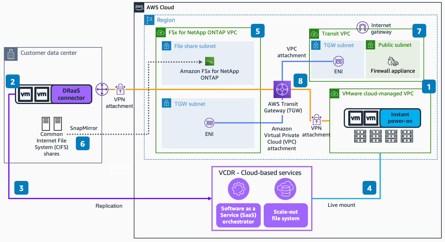
Using VMware VCDR and Amazon FSx for DR Diagram
-
Deploy the VMware Cloud Disaster Recovery (VCDR) pilot light cluster in the VCDR portal. This pilot light cluster will serve as a minimum footprint in VMware Cloud on AWS (VMC) that will scale up in a disaster recovery (DR) event. Without this pilot light cluster, provisioning and configuring the VMC environment would take place after a disaster has been declared, but prior to failover. Note: This will add to the recovery time objective (RTO).
-
Deploy the VCDR DRaaS connector virtual appliance in the on-premises VMware environment. This virtual appliance provides a service connection into VCDR. Define your VM protection groups (groups of VMs with their respective snapshot schedules), the corresponding Recovery Point Objective (RPO), and the backup retention period. These are the DR policies that will be applied to the VMs in the on-premises vSphere environment.
-
The DRaaS connector replicates the VM data from the on-premises vSphere environment to the VCDR cloud-based services.
-
In a DR event, the replicated data in the scale-out file system gets live-mounted into the VCDR pilot light cluster. Once mounted, the failed-over VMs get powered-on and begin serving data.
-
Deploy Amazon FSx for NetApp ONTAP. This service has two storage tiers: primary storage and capacity pool storage. Primary storage is provisioned, high-performance, solid-state drive (SSD) storage, the size of which is set at the time of deployment. Capacity pool storage is a fully-elastic storage tier that grows and shrinks as data is tiered into it.
-
The Common Internet File System (CIFS) is replicated into Amazon FSx for NetApp ONTAP using NetApp SnapMirror.
-
For additional security, deploy a Transit VPC with a firewall appliance to manage the firewall rules for the internet traffic and traffic across various resources.
-
Deploy AWS Transit Gateway with two VPC peering attachments and two VPN connections to allow and manage the network traffic flow across the four components.
Download editable diagram
To customize this reference architecture diagram based on your business needs, download the ZIP file which contains an editable PowerPoint.
Create a free AWS account

Sign up for an AWS account. New accounts include 12 months of AWS Free Tier
Further reading
For additional information, refer to
Diagram history
To be notified about updates to this reference architecture diagram, subscribe to the RSS feed.
| Change | Description | Date |
|---|---|---|
Initial publication | Reference architecture diagram first published. | March 17, 2022 |
Note
To subscribe to RSS updates, you must have an RSS plugin enabled for the browser you are using.
