This whitepaper is for historical reference only. Some content might be outdated and some links might not be available.
Implementing LPWAN IoT solutions with CoAP
This section first provides an overview of the architectural considerations for an implementation of a CoAP-based IoT solution. It then describes typical implementation patterns that AWS customers can use to implement CoAP-based IoT solutions.
Introduction to CoAP
CoAP is an application layer protocol that was
purpose built for constrained devices. It has low overhead and allows simple implementation
on IoT devices. For example, the smallest size of the CoAP message is four bytes, if
omitting tokens, options, and payload. Using CoAP, you can implement HTTP-like
request/response patterns. Because CoAP is based on UDP, implementation using CoAP is more
energy-efficient than when using MQTT or HTTP. You will find a specification of CoAP in
RFC 7252
CoAP client and server
Depending on use case requirements, an IoT device can act as a CoAP client, a CoAP server, or both. Battery-operated LPWAN devices will act as a CoAP client for the purpose of reduction of energy consumption. A mainline-operated LPWAN device can also act as a CoAP server.
CoAP resource model
CoAP is based on a resource model. A resource, in the context of CoAP, is a logical container on the CoAP server. Each CoAP resource is mapped to a Unique Resource Identifier (URI). A CoAP resource URI consists of host, port, path, and query. An example CoAP URI is coaps://host:port/path/to/resource?key=value. To interact with resources, CoAP supports methods such as GET, PUT, POST, and DELETE with semantics and return codes similar (but not identical) to HTTP.
Confirmable and non-confirmable requests
CoAP supports both confirmable and non-confirmable requests. When using confirmable requests, the CoAP server must acknowledge the request with an acknowledgement in response. The response acknowledgement can optionally contain the payload sent by the server. Clients can use the confirmable messages to deal with the packet loss. If CoAP client does not receive an acknowledgement from the server, the CoAP client can perform a retry.
The following figure shows examples for common patterns of using both confirmable and non-confirmable requests. For the requests from the CoAP client to the CoAP server, the figure specifies a CoAP method (for example, POST), URI-path (for example, /temperature), type of message (CONfirmable or NON-confirmable), and—where applicable—payload (for example, “36.6”). For the responses from the CoAP server to the CoAP client, the figure specifies the response code (for example, 2.05 which means “Content”) and—where applicable—payload.

Types of CoAP requests
As mentioned previously, an IoT device can act as a CoAP client, CoAP server, or both. For the use case of telemetry ingestion from battery-operated LPWAN devices, the IoT device will act as a CoAP client.
Block-wise transfer mode
Normal CoAP messages are restricted in size and typically used for small payloads, such
as measurements from the sensors or commands to the actuators. The size restriction results
from factors such as maximum UDP datagram size or maximum MTU size enforced by cellular
network operators. To enable applications to transfer larger amounts of data (for example,
for the purpose of firmware updates), CoAP supports block-wise transfer mode as specified in
RFC 7959
In the following example, a payload with the size of 384 bytes needs to be sent from the server to the client, over a connection limiting the maximum payload size per UDP datagram to 128 bytes. CoAP client performs a GET request, and CoAP server sends three blocks of 128 bytes each.
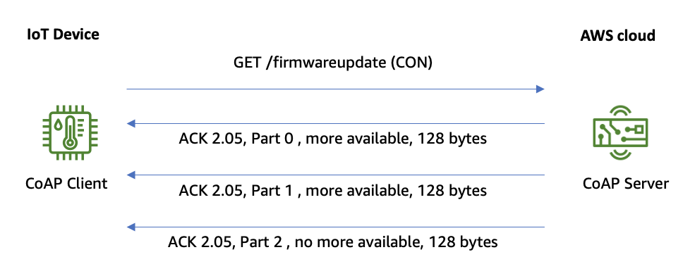
Example of CoAP block-wise transfer
Encryption in transit and device authentication
CoAP provides neither capability for encryption in transit, no dedicated features for
device authentication. For the purpose of encryption in transit and device authentication,
DTLS can be used. You will find more details on DTLS in RFC6347
Architectural considerations
When architecting an IoT solution based on CoAP, AWS recommends several fundamental considerations. First, consider whether your IoT device should take on the role of CoAP client, CoAP server, or both. Battery-powered IoT devices that use LPWAN connectivity should act as CoAP clients for energy efficiency. However, depending on the use case, your IoT device might also need to operate as a CoAP server. In this case, it is important to note that not all implementation patterns described in the following section support IoT devices acting as CoAP servers.
The second consideration is a definition of the CoAP features required for an
implementation of your use case. AWS recommends that you consider both CoAP features which
are required in the short term and CoAP features which may be required at a later point of
time as your IoT solution evolves. This step is important because individual implementation
approaches may differ depending on the subset of CoAP features they support. Examples of
such CoAP features can be support for GET/PUT/POST/DELETE
methods
If you plan to use DTLS as a security layer for CoAP, an analysis of required DTLS
features is also recommended. Examples for such features are support for authentication
methods (for example, No-Sec, Pre-shared keys
(PSK), Raw Public Key Certificates, X.509 certificates
Implementation patterns
When implementing data ingestion and device commands with CoAP, there are three implementation patterns to consider. These patterns differ depending which entity operates the CoAP software components, such as CoAP server or CoAP client. These patterns are: CoAP software components are operated by telco, CoAP software components are operated by an AWS Partner, and CoAP software components are operated by the customers. In the latter case, two different varations shall be distinguished, depending on how the data in transit are secured. The data in transit can be secured by a VPN connection between telco and customer’s account, or by using a communication protocol such as DTLS.
The following diagram illustrates three patterns, including two variations of the latter one:

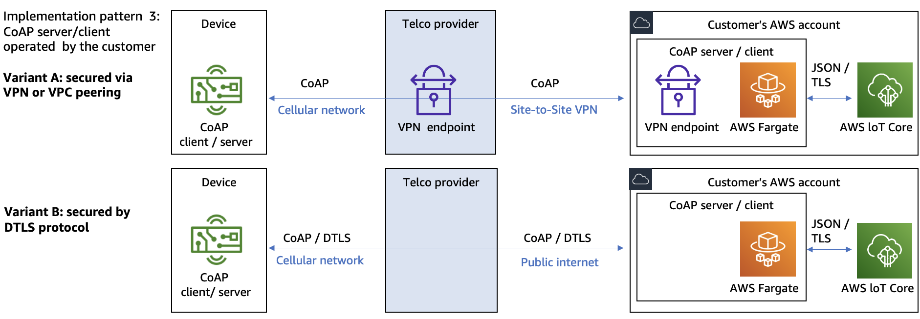
Patterns for implementing IoT solutions with AWS using CoAP
The following sections contain a detailed description of each of these patterns.
Pattern 1: CoAP components are operated by telco
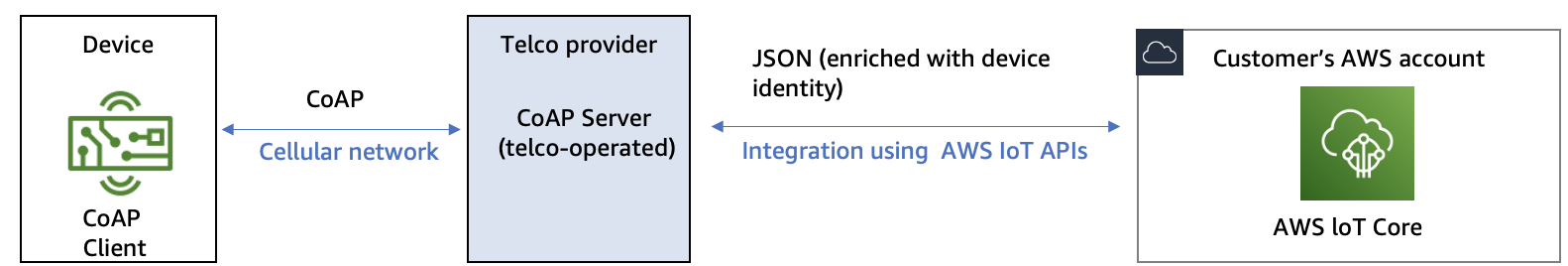
Architecture for CoAP server operated by telco
In this pattern, the telecom provider operates a CoAP endpoint, which acts as a CoAP server. Customers can configure the CoAP endpoint to integrate with the customer’s AWS account. Each time the CoAP client on the IoT device sends a message to the CoAP server, the CoAP server will perform the steps of encapsulation, enrichment, and ingestion into the customer’s account.
In the encapsulation and enrichment step, the CoAP server first encapsulates the binary payload into a JSON message, and then enriches this JSON message with additional useful information. An example of additional information is the International Mobile Subscriber Identity (IMSI) of the IoT device.
Note
The binary payload remains unchanged in this step. If necessary, binary decoding should be performed in the customer’s AWS account.
In the ingestion step, the CoAP server forwards the JSON message to the AWS IoT Core service in the customer’s AWS account. After the data arrive in AWS IoT Core message broker or AWS IoT Core rule engine, it can be further processed by a broad range of AWS services.
If you want to give telco provider access to AWS resources in your account, AWS recommends using IAM roles with external IDs to delegate access of your AWS resources to the telco AWS account.
Refer to the following resource for examples of AWS Partners supporting this pattern:
Pattern 2: CoAP components are operated by an AWS Partner

Architecture for CoAP server operated by an AWS Partner
In this pattern, an AWS Partner operates a CoAP endpoint, which acts as a CoAP server. Customers can configure the CoAP endpoint to integrate with a customer’s AWS account. Each time the CoAP client on the IoT device sends a message to the CoAP server, it will perform the steps of encapsulation and ingestion into the customer’s account.
-
Encapsulation step – The CoAP server encapsulates the binary payload into a JSON message. Note that the binary payload remains unchanged in this step. If necessary, binary decoding should be performed in the customer’s AWS account.
-
Ingestion step – The CoAP server forwards the JSON message to the AWS IoT Core service in the customer’s AWS account. After the data arrive in the AWS IoT Core message broker or AWS IoT Core rule engine, the data can be further processed by a broad range of AWS services.
If you want to give an AWS Partner access to AWS resources in your account, AWS recommends using IAM roles with external IDs to delegate access from your AWS resources to the AWS Partner account.
Refer to the following resources for examples of AWS Partners supporting this pattern:
Pattern 3: CoAP components are operated by the customer
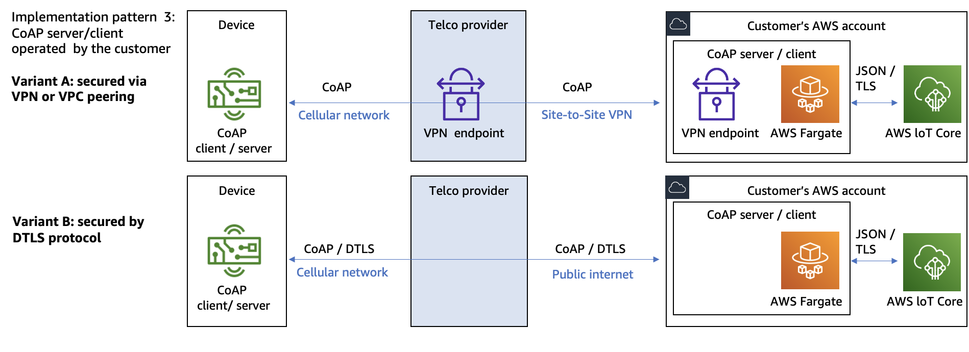
Architecture for CoAP server and client operated by customer
In this pattern, the AWS customer operates a CoAP endpoint in their AWS account. Depending on the use case requirements, the CoAP endpoint can operate as CoAP server, CoAP client, or both. The CoAP endpoint can handle forwarding the incoming CoAP messages to AWS IoT Core, and sending CoAP messages to the IoT devices. To ingest messages to AWS IoT Core, AWS recommends using AWS IoT data plane APIs authorized by IAM mechanisms.
When using this pattern, a mechanism used for securing data in transit needs to be defined. This mechanism will protect the complete path of communication from the IoT device to the customer’s AWS account. The first consideration is to protect the data in transit between the IoT device and the telco provider’s infrastructure. The second consideration is to protect the data in transit between the telco provider’s infrastructure and the customer’s AWS account. There are two possible variants for securing data in transit:
Securing data in transit with a VPN connection between telco and customer’s AWS account

Using VPN to secure data in transit
In this variant, customers rely on the telco provider’s infrastructure for protection data in transit between the IoT device and the telco provider’s infrastructure. No protocol-level security is used, and CoAP is used in NoSec mode. To protect data in transit between telco provider’s infrastructure and the customer’s AWS account, a VPN connection is established between the telco provider and the customer’s AWS account.
For further information on using VPN, review the AWS VPN
Securing data in transit with protocols as DTLS
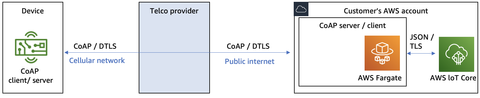
Using DTLS to secure data in transit
In this variant, customers use DTLS protocol as a mechanism for infrastructure for protection data in transit between the IoT device and telco provider’s infrastructure, and between telco provider’s infrastructure and the customer’s AWS account.
