This whitepaper is for historical reference only. Some content might be outdated and some links might not be available.
Floating IP pattern for HA between active–standby stateful servers
The floating IP design pattern is a well-known mechanism to achieve automatic failover between an active and standby pair of hardware nodes (media servers). A static secondary virtual IP address is assigned to the active node. Continuous monitoring between the active and standby nodes detects failure. If the active node fails, the monitoring script assigns the virtual IP to the ready standby node and the standby node takes over the primary active function. In this way, the virtual IP floats between the active and standby node.
Applicability in RTC solutions
It is not always possible to have multiple active instances of the same component in service, such as an active–active cluster of N nodes. An active–standby configuration provides the best mechanism for HA. For example, the stateful components in an RTC solution, such as the media server or conferencing server, or even an SBC or database server, are well-suited for an active–standby setup. An SBC or media server has several long running sessions or channels active at a given time, and in the case of the SBC active instance failing, the endpoints can reconnect to the standby node without any client-side configuration due to the floating IP.
Implementation on AWS
You can implement this pattern on AWS using core capabilities in Amazon Elastic Compute Cloud (Amazon EC2), Amazon EC2 API, Elastic IP addresses, and support on Amazon EC2 for secondary private IP addresses.
To implement the floating IP pattern on AWS:
-
Launch two EC2 instances to assume the roles of primary and secondary nodes, where the primary is assumed to be in active state by default.
-
Assign an additional secondary private IP address to the primary EC2 instance.
-
An elastic IP address, which is similar to a virtual IP (VIP), is associated with the secondary private address. This secondary private address is the address that is used by external endpoints to access the application.
-
Some operating system (OS) configuration is required to make the secondary IP address added as an alias to the primary network interface.
-
The application must bind to this elastic IP address. In the case of Asterisk software, you can configure the binding through advanced Asterisk SIP settings.
-
Run a monitoring script—custom, KeepAlive on Linux, Corosync, and so on—on each node to monitor the state of the peer node. In the event, that the current active node fails, the peer detects this failure, and invokes the Amazon EC2 API to reassign the secondary private IP address to itself.
Therefore, the application that was listening on the VIP associated with the secondary private IP address becomes available to endpoints via the standby node.
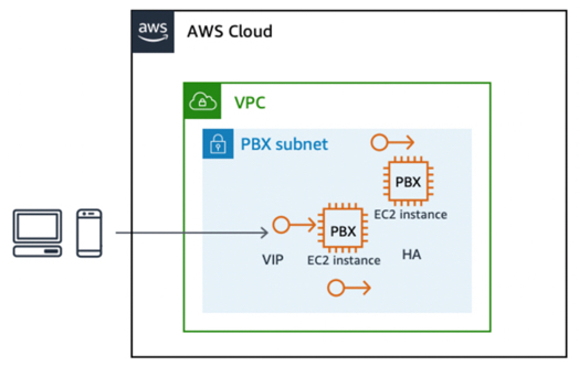
Failover between stateful EC2 instances using an elastic IP address
Benefits
This approach is a reliable low-budget solution that protects against failures at the EC2 instance, infrastructure, or application level.
Limitations and extensibility
This design pattern is typically limited to within a single Availability Zone. It can be implemented across two Availability Zones, but with a variation. In this case, the Floating Elastic IP address is re-associated between active and standby node in different Availability Zones via the re-associate elastic IP address API available. In the failover implementation shown in the preceding figure, calls in progress are dropped and endpoints must reconnect. It is possible to extend this implementation with replication of underlying session data to provide seamless failover of sessions or media continuity as well.
Load balancing for scalability and HA with WebRTC and SIP
Load balancing a cluster of active instances based on predefined rules, such as round robin, affinity or latency, and so on, is a design pattern widely popularized by the stateless nature of HTTP requests. In fact, load balancing is a viable option in case of many RTC application components.
The load balancer acts as the reverse proxy or entry point for requests to the desired application, which itself is configured to run in multiple active nodes simultaneously. At any given point in time, the load balancer directs a user request to one of the active nodes in the defined cluster. Load balancers perform a health check against the nodes in their target cluster and do not send an incoming request to a node that fails the health check. Therefore, a fundamental degree of high availability is achieved by load balancing. Also, because a load balancer performs active and passive health checks against all cluster nodes in sub-second intervals, the time for failover is near instantaneous.
The decision on which node to direct is based on system rules defined in the load balancer, including:
-
Round robin
-
Session or IP affinity, which ensures that multiple requests within a session or from the same IP are sent to the same node in the cluster
-
Latency based
-
Load based
Applicability in RTC architectures
The WebRTC protocol makes it possible for WebRTC Gateways to be easily load balanced
via an HTTP-based load balancer, such as Elastic Load Balancing
Load balancing on AWS for WebRTC using Application Load Balancer and Auto Scaling
In the case of WebRTC based communications, Elastic Load Balancing provides a fully managed, highly available and scalable load balancer to serve as the entry point for requests, which are then directed to a target cluster of EC2 instances associated with Elastic Load Balancing. Because WebRTC requests are stateless, you can use Amazon EC2 Auto Scaling, to provide fully automated and controllable scalability, elasticity, and high availability.
The Application Load Balancer provides a fully managed load balancing service that is highly available using multiple Availability Zones, and scalable. This supports the load balancing of WebSocket requests that handle the signaling for WebRTC applications and bidirectional communication between the client and server using a long running TCP connection. The Application Load Balancer also supports content-based routing and sticky sessions, routing requests from the same client to the same target using load balancer generated cookies. If you enable sticky sessions, the same target receives the request and can use the cookie to recover the session context.
The following figure shows the target topology.

WebRTC scalability and high availability architecture
Implementation for SIP using Network Load Balancer or an AWS Marketplace product
In the case of SIP-based communications, the connections are made over TCP or UDP, with the majority of RTC applications using UDP. If SIP/TCP is the signal protocol of choice, then it is feasible to use the Network Load Balancer for fully managed, highly available, scalable and performance load balancing.
A Network Load Balancer operates at the connection level (Layer four), routing
connections to targets such as Amazon EC2 instances, containers, and IP addresses based on IP
protocol data. Ideal for TCP or UDP traffic load balancing, network load balancing is
capable of handling millions of requests per second while maintaining ultra-low latencies.
It is integrated with other popular AWS services, such as Amazon EC2 Auto Scaling, Amazon Elastic Container Service
If SIP connections are initiated, another option is to use AWS Marketplace
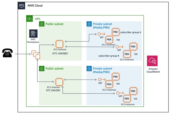
SIP-based RTC scalability with AWS Marketplace product
