Example routing options
The following topics describe routing for specific gateways or connections in your VPC.
Contents
Routing to an internet gateway
You can make a subnet a public subnet by adding a route in your subnet route table to an
internet gateway. To do this, create and attach an internet gateway to your VPC, and
then add a route with a destination of 0.0.0.0/0 for IPv4 traffic or
::/0 for IPv6 traffic, and a target of the internet gateway ID
(igw-xxxxxxxxxxxxxxxxx).
| Destination | Target |
|---|---|
| 0.0.0.0/0 | igw-id |
| ::/0 | igw-id |
For more information, see Enable internet access for a VPC using an internet gateway.
Routing to a NAT device
To enable instances in a private subnet to connect to the internet, you can create a NAT
gateway or launch a NAT instance in a public subnet. Then add a route for the
private subnet's route table that routes IPv4 internet traffic
(0.0.0.0/0) to the NAT device.
| Destination | Target |
|---|---|
| 0.0.0.0/0 | nat-gateway-id |
You can also create more specific routes to other targets to avoid unnecessary data processing charges for using a NAT gateway, or to route certain traffic privately. In the following example, Amazon S3 traffic (pl-xxxxxxxx, a prefix list that contains the IP address ranges for Amazon S3 in a specific Region) is routed to a gateway VPC endpoint, and 10.25.0.0/16 traffic is routed to a VPC peering connection. These IP address ranges are more specific than 0.0.0.0/0. When instances send traffic to Amazon S3 or the peer VPC, the traffic is sent to the gateway VPC endpoint or the VPC peering connection. All other traffic is sent to the NAT gateway.
| Destination | Target |
|---|---|
| 0.0.0.0/0 | nat-gateway-id |
pl-xxxxxxxx |
vpce-id |
| 10.25.0.0/16 | pcx-id |
For more information, see NAT devices.
Routing to a virtual private gateway
You can use an AWS Site-to-Site VPN connection to enable instances in your VPC to communicate with
your own network. To do this, create and attach a virtual private gateway to your
VPC. Then add a route in your subnet route table with the destination of your
network and a target of the virtual private gateway
(vgw-xxxxxxxxxxxxxxxxx).
| Destination | Target |
|---|---|
| 10.0.0.0/16 | vgw-id |
You can then create and configure your Site-to-Site VPN connection. For more information, see What is AWS Site-to-Site VPN? and Route tables and VPN route priority in the AWS Site-to-Site VPN User Guide.
A Site-to-Site VPN connection on a virtual private gateway does not support IPv6 traffic. However, we support IPv6 traffic routed through a virtual private gateway to an AWS Direct Connect connection. For more information, see the AWS Direct Connect User Guide.
Routing to an AWS Outposts local gateway
This section describes routing table configurations for routing to an AWS Outposts local gateway.
Contents
Enable traffic between Outpost subnets and your on-premises network
Subnets that are in VPCs associated with AWS Outposts can have an additional target
type of a local gateway. Consider the case where you want to have the local gateway
route traffic with a destination address of 192.168.10.0/24 to the customer
network. To do this, add the following route with the destination network and a
target of the local gateway (lgw-xxxx).
| Destination | Target |
|---|---|
| 192.168.10.0/24 | lgw-id |
Enable traffic between subnets in the same VPC across Outposts
You can establish communication between subnets that are in the same VPC across different Outposts using Outpost local gateways and your on-premise network.
You can use this feature to build architectures similar to multi-Availability Zone (AZ) architectures for your on-premise applications running on Outposts racks by establishing connectivity between Outposts racks that are anchored to different AZs.
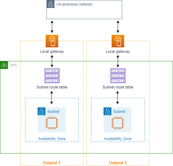
To enable this feature, add a route to your Outpost rack subnet route table that is more specific than the local route in that route table and has a target type of local gateway. The destination of the route must match the entire IPv4 block of the subnet in your VPC that is in another Outpost. Repeat this configuration for all the Outpost subnets that need to communicate.
Important
To use this feature, you must use direct VPC routing. You cannot use your own customer-owned IP addresses.
Your on-premise network that the Outposts local gateways are connected to must have the required routing so that subnets can access to each other.
If you want to use security groups for resources in the subnets, you must use rules that include IP address ranges as source or destination in the Outpost subnets. You cannot use security group IDs.
Existing Outposts racks may require an update to enable support for intra-VPC communication across multiple Outposts. If this feature doesn't work for you, contact AWS Support.
Example
For a VPC with a CIDR of 10.0.0.0/16, an Outpost 1 subnet with a CIDR of 10.0.1.0/24, and an Outpost 2 subnet with a CIDR of 10.0.2.0/24, the entry for Outpost 1 subnet’s route table would be as follows:
| Destination | Target |
|---|---|
| 10.0.0.0/16 | Local |
| 10.0.2.0/24 | lgw-1-id |
The entry for Outpost 2 subnet’s route table would be as follows:
| Destination | Target |
|---|---|
| 10.0.0.0/16 | Local |
| 10.0.1.0/24 | lgw-2-id |
Routing to a VPC peering connection
A VPC peering connection is a networking connection between two VPCs that allows you to route traffic between them using private IPv4 addresses. Instances in either VPC can communicate with each other as if they are part of the same network.
To enable the routing of traffic between VPCs in a VPC peering connection, you must add a route to one or more of your subnet route tables that points to the VPC peering connection. This allows you to access all or part of the CIDR block of the other VPC in the peering connection. Similarly, the owner of the other VPC must add a route to their subnet route table to route traffic back to your VPC.
For example, you have a VPC peering connection (pcx-11223344556677889)
between two VPCs, with the following information:
-
VPC A: CIDR block is 10.0.0.0/16
-
VPC B: CIDR block is 172.31.0.0/16
To enable traffic between the VPCs and allow access to the entire IPv4 CIDR block of either VPC, the VPC A route table is configured as follows.
| Destination | Target |
|---|---|
| 10.0.0.0/16 | Local |
| 172.31.0.0/16 | pcx-11223344556677889 |
The VPC B route table is configured as follows.
| Destination | Target |
|---|---|
| 172.31.0.0/16 | Local |
| 10.0.0.0/16 | pcx-11223344556677889 |
Your VPC peering connection can also support IPv6 communication between instances in the VPCs, if the VPCs and instances are enabled for IPv6 communication. To enable the routing of IPv6 traffic between VPCs, you must add a route to your route table that points to the VPC peering connection to access all or part of the IPv6 CIDR block of the peer VPC.
For example, using the same VPC peering connection (pcx-11223344556677889)
above, assume the VPCs have the following information:
-
VPC A: IPv6 CIDR block is
2001:db8:1234:1a00::/56 -
VPC B: IPv6 CIDR block is
2001:db8:5678:2b00::/56
To enable IPv6 communication over the VPC peering connection, add the following route to the subnet route table for VPC A.
| Destination | Target |
|---|---|
| 10.0.0.0/16 | Local |
| 172.31.0.0/16 | pcx-11223344556677889 |
| 2001:db8:5678:2b00::/56 | pcx-11223344556677889 |
Add the following route to the route table for VPC B.
| Destination | Target |
|---|---|
| 172.31.0.0/16 | Local |
| 10.0.0.0/16 | pcx-11223344556677889 |
| 2001:db8:1234:1a00::/56 | pcx-11223344556677889 |
For more information about VPC peering connections, see the Amazon VPC Peering Guide.
Routing to a gateway VPC endpoint
A gateway VPC endpoint enables you to create a private connection between your VPC and
another AWS service. When you create a gateway endpoint, you specify the subnet
route tables in your VPC that are used by the gateway endpoint. A route is
automatically added to each of the route tables with a destination that specifies
the prefix list ID of the service
(pl-), and a target with the
endpoint ID (xxxxxxxxvpce-). You
cannot explicitly delete or modify the endpoint route, but you can change the route
tables that are used by the endpoint.xxxxxxxxxxxxxxxxx
For more information about routing for endpoints, and the implications for routes to AWS services, see Routing for gateway endpoints.
Routing to an egress-only internet gateway
You can create an egress-only internet gateway for your VPC to enable instances in a
private subnet to initiate outbound communication to the internet, but prevent the
internet from initiating connections with the instances. An egress-only internet
gateway is used for IPv6 traffic only. To configure routing for an egress-only
internet gateway, add a route in the private subnet's route table that routes IPv6
internet traffic (::/0) to the egress-only internet gateway.
| Destination | Target |
|---|---|
| ::/0 | eigw-id |
For more information, see Enable outbound IPv6 traffic using an egress-only internet gateway.
Routing for a transit gateway
When you attach a VPC to a transit gateway, you need to add a route to your subnet route table for traffic to route through the transit gateway.
Consider the following scenario where you have three VPCs that are attached to a transit gateway. In this scenario, all attachments are associated with the transit gateway route table and propagate to the transit gateway route table. Therefore, all attachments can route packets to each other, with the transit gateway serving as a simple layer 3 IP hub.
For example, you have two VPCs, with the following information:
-
VPC A: 10.1.0.0/16, attachment ID tgw-attach-11111111111111111
-
VPC B: 10.2.0.0/16, attachment ID tgw-attach-22222222222222222
To enable traffic between the VPCs and allow access to the transit gateway, the VPC A route table is configured as follows.
| Destination | Target |
|---|---|
| 10.1.0.0/16 | local |
| 10.0.0.0/8 | tgw-id |
The following is an example of the transit gateway route table entries for the VPC attachments.
| Destination | Target |
|---|---|
| 10.1.0.0/16 | tgw-attach-11111111111111111 |
| 10.2.0.0/16 | tgw-attach-22222222222222222 |
For more information about transit gateway route tables, see Routing in Amazon VPC Transit Gateways.
Routing for a middlebox appliance
You can add middlebox appliances into the routing paths for your VPC. The following are possible use cases:
-
Intercept traffic that enters your VPC through an internet gateway or a virtual private gateway by directing it to a middlebox appliance in your VPC. You can use the middlebox routing wizard to have AWS automatically configure the appropriate route tables for your gateway, middlebox, and destination subnet. For more information, see Middlebox routing wizard.
-
Direct traffic between two subnets to a middlebox appliance. You can do so by creating a route for one subnet route table that matches the subnet CIDR of the other subnet and specifies a Gateway Load Balancer endpoint, NAT gateway, Network Firewall endpoint, or the network interface for an appliance as a target. Alternatively, to redirect all traffic from the subnet to any other subnet, replace the target of the local route with a Gateway Load Balancer endpoint, NAT gateway, or network interface.
You can configure the appliance to suit your needs. For example, you can configure a security appliance that screens all traffic, or a WAN acceleration appliance. The appliance is deployed as an Amazon EC2 instance in a subnet in your VPC, and is represented by an elastic network interface (network interface) in your subnet.
If you enable route propagation for the destination subnet route table, be aware of route priority. We prioritize the most specific route, and if the routes match, we prioritize static routes over propagated routes. Review your routes to ensure that traffic is routed correctly and that there are no unintended consequences if you enable or disable route propagation (for example, route propagation is required for an AWS Direct Connect connection that supports jumbo frames).
To route inbound VPC traffic to an appliance, you associate a route table with the internet gateway or virtual private gateway, and specify the network interface of your appliance as the target for VPC traffic. For more information, see Gateway route tables. You can also route outbound traffic from your subnet to a middlebox appliance in another subnet.
For middlebox routing examples, see Middlebox scenarios.
Contents
Appliance considerations
You can choose a third-party appliance from AWS Marketplace
-
The appliance must be configured in a separate subnet to the source or destination traffic.
-
You must disable source/destination checking on the appliance. For more information, see Changing the Source or Destination Checking in the Amazon EC2 User Guide.
-
You cannot route traffic between hosts in the same subnet through an appliance.
-
The appliance does not have to perform network address translation (NAT).
-
You can add a route to your route tables that is more specific than the local route. You can use more specific routes to redirect traffic between subnets within a VPC (East-West traffic) to a middlebox appliance. The destination of the route must match the entire IPv4 or IPv6 CIDR block of a subnet in your VPC.
-
To intercept IPv6 traffic, ensure that your VPC, subnet, and appliance support IPv6.
Routing traffic between a gateway and an appliance
To route inbound VPC traffic to an appliance, you associate a route table with the internet gateway or virtual private gateway, and specify the network interface of your appliance as the target for VPC traffic. In the following example, the VPC has an internet gateway, an appliance, and a subnet with instances. Traffic from the internet is routed through an appliance.

Associate this route table with your internet gateway or virtual private gateway. The first entry is the local route. The second entry sends IPv4 traffic destined for the subnet to the network interface for the appliance. This route is more specific than the local route.
| Destination | Target |
|---|---|
VPC CIDR |
Local |
Subnet CIDR |
Appliance network interface ID |
Alternatively, you can replace the target for the local route with the network interface of the appliance. You can do this to ensure that all traffic is automatically routed to the appliance, including traffic destined for subnets that you add to the VPC in the future.
| Destination | Target |
|---|---|
VPC CIDR |
Appliance network interface ID |
To route traffic from your subnet to an appliance in another subnet, add a
route to your subnet route table that routes traffic to the appliance's network
interface. The destination must be less specific than the destination for the
local route. For example, for traffic destined for the internet, specify
0.0.0.0/0 (all IPv4 addresses) for the destination.
| Destination | Target |
|---|---|
VPC CIDR |
Local |
| 0.0.0.0/0 | Appliance network interface ID |
Then, in the route table associated with the appliance's subnet, add a route that sends the traffic back to the internet gateway or virtual private gateway.
| Destination | Target |
|---|---|
VPC CIDR |
Local |
| 0.0.0.0/0 | igw-id |
Routing inter-subnet traffic to an appliance
You can route traffic destined for a specific subnet to the network interface of an appliance. In the following example, the VPC contains two subnets and an appliance. Traffic between the subnets is routed through an appliance.
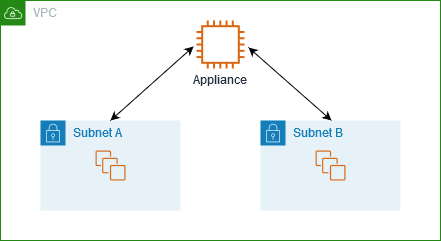
Security groups
When you route traffic between instances in different subnets through a middlebox appliance, the security groups for both instances must allow traffic to flow between the instances. The security group for each instance must reference the private IP address of the other instance, or the CIDR range of the subnet that contains the other instance, as the source. If you reference the security group of the other instance as the source, this does not allow traffic to flow between the instances.
Routing
The following is an example route table for subnet A. The first entry enables instances in the VPC to communicate with each other. The second entry routes all traffic from subnet A to subnet B to the network interface of the appliance.
| Destination | Target |
|---|---|
VPC CIDR |
Local |
Subnet B CIDR |
Appliance network interface ID |
The following is an example route table for subnet B. The first entry enables instances in the VPC to communicate with each other. The second entry routes all traffic from subnet B to subnet A to the network interface of the appliance.
| Destination | Target |
|---|---|
VPC CIDR |
Local |
Subnet A CIDR |
Appliance network interface ID |
Alternatively, you can replace the target for the local route with the network interface of the appliance. You can do this to ensure that all traffic is automatically routed to the appliance, including traffic destined for subnets that you add to the VPC in the future.
| Destination | Target |
|---|---|
VPC CIDR |
Appliance network interface ID |
Routing using a prefix list
If you frequently reference the same set of CIDR blocks across your AWS resources, you can create a customer-managed prefix list to group them together. You can then specify the prefix list as the destination in your route table entry. You can later add or remove entries for the prefix list without needing to update your route tables.
For example, you have a transit gateway with multiple VPC attachments. The VPCs must be able to communicate with two specific VPC attachments that have the following CIDR blocks:
-
10.0.0.0/16
-
10.2.0.0/16
You create a prefix list with both entries. In your subnet route tables, you create a route and specify the prefix list as the destination, and the transit gateway as the target.
| Destination | Target |
|---|---|
| 172.31.0.0/16 | Local |
| pl-123abc123abc123ab | tgw-id |
The maximum number of entries for the prefix lists equals the same number of entries in the route table.
Routing to a Gateway Load Balancer endpoint
A Gateway Load Balancer enables you to distribute traffic to a fleet of virtual appliances, such as firewalls. You can create a Gateway Load Balancer, configure a Gateway Load Balancer endpoint service, and then create a Gateway Load Balancer endpoint in your VPC to connect it to the service.
To route your traffic to the Gateway Load Balancer (for example, for security inspection), specify the Gateway Load Balancer endpoint as a target in your route tables.
For an example of a security appliances behind a Gateway Load Balancer, see Configure middlebox traffic routing and inspection in a VPC.
To specify the Gateway Load Balancer endpoint in the route table, use the ID of the VPC endpoint. For example to route traffic for 10.0.1.0/24 to a Gateway Load Balancer endpoint, add the following route.
| Destination | Target |
|---|---|
| 10.0.1.0/24 | vpc-endpoint-id |
When using a Gateway Load Balancer endpoint as a target, you cannot specify a prefix list as a destination. If you attempt to create or replace a prefix list route targeting a VPC Endpoint, you'll receive the error: "Cannot create or replace a prefix list route targeting a VPC Endpoint."
For more information, see Gateway Load Balancers.
