NAT gateway use cases
The following are example use cases for public and private NAT gateways.
Scenarios
Access the internet from a private subnet
You can use a public NAT gateway to enable instances in a private subnet to send outbound traffic to the internet, while preventing the internet from establishing connections to the instances.
Overview
The following diagram illustrates this use case. There are two Availability Zones, with two subnets in each Availability Zone. The route table for each subnet determines how traffic is routed. In Availability Zone A, the instances in the public subnet can reach the internet through a route to the internet gateway, while the instances in the private subnet have no route to the internet. In Availability Zone B, the public subnet contains a NAT gateway, and the instances in the private subnet can reach the internet through a route to the NAT gateway in the public subnet. Both private and public NAT gateways map the source private IPv4 address of the instances to the private IPv4 address of the private NAT gateway, but in the case of a public NAT gateway, the internet gateway then maps the private IPv4 address of the public NAT gateway to the Elastic IP address associated with the NAT gateway. When sending response traffic to the instances, whether it's a public or private NAT gateway, the NAT gateway translates the address back to the original source IP address.
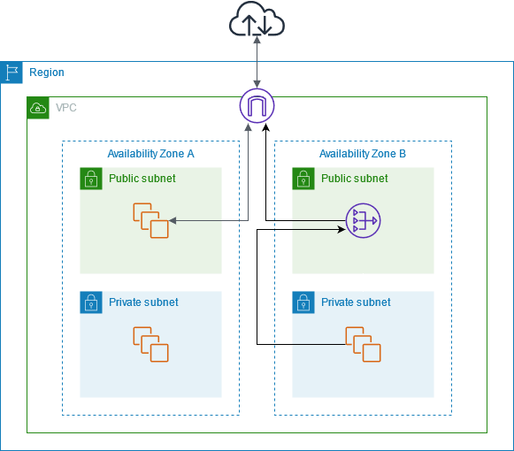
Note that if the instances in the private subnet in Availability Zone A also need to reach the internet, you can create a route from this subnet to the NAT gateway in Availability Zone B. Alternatively, you can improve resiliency by creating a NAT gateway in each Availability Zone that contains resources that require internet access. For an example diagram, see Example: VPC with servers in private subnets and NAT.
Routing
The following is the route table associated with the public subnet in Availability Zone A. The first entry is the local route; it enables the instances in the subnet to communicate with other instances in the VPC using private IP addresses. The second entry sends all other subnet traffic to the internet gateway, which enables the instances in the subnet to access the internet.
| Destination | Target |
|---|---|
VPC CIDR |
local |
| 0.0.0.0/0 | internet-gateway-id |
The following is the route table associated with the private subnet in Availability Zone A. The entry is the local route, which enables the instances in the subnet to communicate with other instances in the VPC using private IP addresses. The instances in this subnet have no access to the internet.
| Destination | Target |
|---|---|
VPC CIDR |
local |
The following is the route table associated with the public subnet in Availability Zone B. The first entry is the local route, which enables the instances in the subnet to communicate with other instances in the VPC using private IP addresses. The second entry sends all other subnet traffic to the internet gateway, which enables the NAT gateway in the subnet to access the internet.
| Destination | Target |
|---|---|
VPC CIDR |
local |
| 0.0.0.0/0 | internet-gateway-id |
The following is the route table associated with the private subnet in Availability Zone B. The first entry is the local route; it enables the instances in the subnet to communicate with other instances in the VPC using private IP addresses. The second entry sends all other subnet traffic to the NAT gateway.
| Destination | Target |
|---|---|
VPC CIDR |
local |
| 0.0.0.0/0 | nat-gateway-id |
For more information, see Manage subnet route tables.
Test the public NAT gateway
After you've created your NAT gateway and updated your route tables, you can ping remote addresses on the internet from an instance in your private subnet to test whether it can connect to the internet. For an example of how to do this, see Test the internet connection.
If you can connect to the internet, you can also test whether internet traffic is routed through the NAT gateway:
-
Trace the route of traffic from an instance in your private subnet. To do this, run the
traceroutecommand from a Linux instance in your private subnet. In the output, you should see the private IP address of the NAT gateway in one of the hops (usually the first hop). -
Use a third-party website or tool that displays the source IP address when you connect to it from an instance in your private subnet. The source IP address should be the Elastic IP address of the NAT gateway.
If these tests fail, see Troubleshoot NAT gateways.
Test the internet connection
The following example demonstrates how to test whether an instance in a private subnet can connect to the internet.
-
Launch an instance in your public subnet (use this as a bastion host). In the launch wizard, ensure that you select an Amazon Linux AMI, and assign a public IP address to your instance. Ensure that your security group rules allow inbound SSH traffic from the range of IP addresses for your local network, and outbound SSH traffic to the IP address range of your private subnet (you can also use
0.0.0.0/0for both inbound and outbound SSH traffic for this test). -
Launch an instance in your private subnet. In the launch wizard, ensure that you select an Amazon Linux AMI. Do not assign a public IP address to your instance. Ensure that your security group rules allow inbound SSH traffic from the private IP address of your instance that you launched in the public subnet, and all outbound ICMP traffic. You must choose the same key pair that you used to launch your instance in the public subnet.
-
Configure SSH agent forwarding on your local computer, and connect to your bastion host in the public subnet. For more information, see To configure SSH agent forwarding for Linux or macOS or To configure SSH agent forwarding for Windows.
-
From your bastion host, connect to your instance in the private subnet, and then test the internet connection from your instance in the private subnet. For more information, see To test the internet connection.
To configure SSH agent forwarding for Linux or macOS
From your local machine, add your private key to the authentication agent.
For Linux, use the following command.
ssh-add -c mykeypair.pemFor macOS, use the following command.
ssh-add -K mykeypair.pemConnect to your instance in the public subnet using the
-Aoption to enable SSH agent forwarding, and use the instance's public address, as shown in the following example.ssh -A ec2-user@54.0.0.123
To configure SSH agent forwarding for Windows
You can use the OpenSSH client available in Windows, or install your preferred SSH client (for example, PuTTY).
To test the internet connection
From your instance in the public subnet, connect to your instance in your private subnet by using its private IP address as shown in the following example.
ssh ec2-user@10.0.1.123From your private instance, test that you can connect to the internet by running the
pingcommand for a website that has ICMP enabled.ping ietf.orgPING ietf.org (4.31.198.44) 56(84) bytes of data. 64 bytes from mail.ietf.org (4.31.198.44): icmp_seq=1 ttl=47 time=86.0 ms 64 bytes from mail.ietf.org (4.31.198.44): icmp_seq=2 ttl=47 time=75.6 ms ...Press Ctrl+C on your keyboard to cancel the
pingcommand. If thepingcommand fails, see Instances cannot access the internet.(Optional) If you no longer require your instances, terminate them. For more information, see Terminate your instance in the Amazon EC2 User Guide.
Access your network using allow-listed IP addresses
You can use a private NAT gateway to enable communication from your VPCs to your on-premises network using a pool of allow-listed addresses. Instead of assigning each instance a separate IP address from the allow-listed IP address range, you can route traffic from the subnet that is destined for the on-premises network through a private NAT gateway with an IP address from the allow-listed IP address range.
Overview
The following diagram shows how instances can access on-premises resources through AWS VPN. Traffic from the instances is routed to a virtual private gateway, over the VPN connection, to the customer gateway, and then to the destination in the on-premises network. However, suppose that the destination allows traffic only from a specific IP address range, such as 100.64.1.0/28. This would prevent traffic from these instances from reaching the on-premises network.
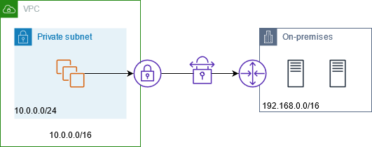
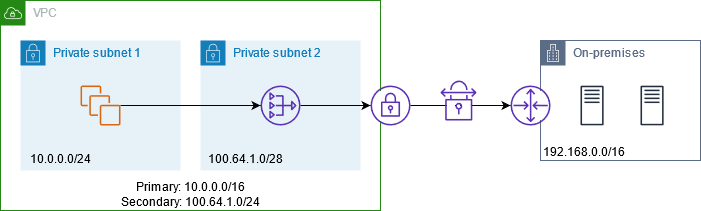
The following diagram shows the key components of the configuration for this scenario. The VPC has its original IP address range plus the allowed IP address range. The VPC has a subnet from the allowed IP address range with a private NAT gateway. Traffic from the instances that is destined for the on-premises network is sent to the NAT gateway before being routed to the VPN connection. The on-premises network receives the traffic from the instances with the source IP address of the NAT gateway, which is from the allowed IP address range.
Resources
Create or update resources as follows:
-
Associate the allowed IP address range with the VPC.
-
Create a subnet in the VPC from the allowed IP address range.
-
Create a private NAT gateway in the new subnet.
-
Update the route table for the subnet with the instances to send traffic destined for the on-premises network to the NAT gateway. Add a route to the route table for the subnet with the private NAT gateway that sends traffic destined for the on-premises network to the virtual private gateway.
Routing
The following is the route table associated with the first subnet. There is a local route for each VPC CIDR. Local routes enable resources in the subnet to communicate with other resources in the VPC using private IP addresses. The third entry sends traffic destined for the on-premises network to the private NAT gateway.
| Destination | Target |
|---|---|
10.0.0.0/16 |
local |
100.64.1.0/24 |
local |
192.168.0.0/16 |
nat-gateway-id |
The following is the route table associated with the second subnet. There is a local route for each VPC CIDR. Local routes enable resources in the subnet to communicate with other resources in the VPC using private IP addresses. The third entry sends traffic destined for the on-premises network to the virtual private gateway.
| Destination | Target |
|---|---|
10.0.0.0/16 |
local |
100.64.1.0/24 |
local |
192.168.0.0/16 |
vgw-id |
Enable communication between overlapping networks
You can use a private NAT gateway to enable communication between networks even if they have overlapping CIDR ranges. For example, suppose that the instances in VPC A need to access the services provided by the instances in VPC B.
Overview
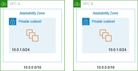
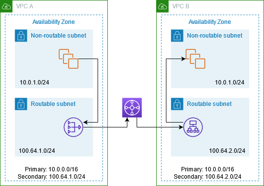
The following diagram shows the key components of the configuration for this scenario. First, your IP management team determines which address ranges can overlap (non-routable address ranges) and which can't (routable address ranges). The IP management team allocates address ranges from the pool of routable address ranges to projects on request.
Each VPC has its original IP address range, which is non-routable, plus the routable IP address range assigned to it by the IP management team. VPC A has a subnet from its routable range with a private NAT gateway. The private NAT gateway gets its IP address from its subnet. VPC B has a subnet from its routable range with an Application Load Balancer. The Application Load Balancer gets its IP addresses from its subnets.
Traffic from an instance in the non-routable subnet of VPC A that is destined for the instances in the non-routable subnet of VPC B is sent through the private NAT gateway and then routed to the transit gateway. The transit gateway sends the traffic to the Application Load Balancer, which routes the traffic to one of the target instances in the non-routable subnet of VPC B. The traffic from the transit gateway to the Application Load Balancer has the source IP address of the private NAT gateway. Therefore, response traffic from the load balancer uses the address of the private NAT gateway as its destination. The response traffic is sent to the transit gateway and then routed to the private NAT gateway, which translates the destination to the instance in the non-routable subnet of VPC A.
Resources
Create or update resources as follows:
-
Associate the assigned routable IP address ranges with their respective VPCs.
-
Create a subnet in VPC A from its routable IP address range, and create a private NAT gateway in this new subnet.
-
Create a subnet in VPC B from its routable IP address range, and create an Application Load Balancer in this new subnet. Register the instances in the non-routable subnet with the target group for the load balancer.
-
Create a transit gateway to connect the VPCs. Be sure to disable route propagation. When you attach each VPC to the transit gateway, use the routable address range of the VPC.
-
Update the route table of the non-routable subnet in VPC A to send all traffic destined for the routable address range of VPC B to the private NAT gateway. Update the route table of the routable subnet in VPC A to send all traffic destined for the routable address range of VPC B to the transit gateway.
-
Update the route table of the routable subnet in VPC B to send all traffic destined for the routable address range of VPC A to the transit gateway.
Routing
The following is the route table for the non-routable subnet in VPC A.
| Destination | Target |
|---|---|
10.0.0.0/16 |
local |
100.64.1.0/24 |
local |
100.64.2.0/24 |
nat-gateway-id |
The following is the route table for the routable subnet in VPC A.
| Destination | Target |
|---|---|
10.0.0.0/16 |
local |
100.64.1.0/24 |
local |
100.64.2.0/24 |
transit-gateway-id |
The following is the route table for the non-routable subnet in VPC B.
| Destination | Target |
|---|---|
10.0.0.0/16 |
local |
100.64.2.0/24 |
local |
The following is the route table for the routable subnet in VPC B.
| Destination | Target |
|---|---|
10.0.0.0/16 |
local |
100.64.2.0/24 |
local |
100.64.1.0/24 |
transit-gateway-id |
The following is the transit gateway route table.
| CIDR | Attachment | Route type |
|---|---|---|
100.64.1.0/24 |
Attachment for VPC A |
Static |
100.64.2.0/24 |
Attachment for VPC B |
Static |
