This whitepaper is for historical reference only. Some content might be outdated and some links might not be available.
Implementing LPWAN IoT solutions on AWS using Sigfox
When implementing an IoT solution with Sigfox, AWS customers can process uplink data from their Sigfox devices (for example, sensor telemetry) and send downlink data to their Sigfox devices (for example, device configuration change). However, the implementation approaches for uplink and downlink vary significantly. Therefore, both approaches will be described separately in the following sections.
Implementing uplink from Sigfox devices to AWS Cloud
The following diagram provides an overview of an IoT solution for processing uplink data from the Sigfox devices:

Example architecture for processing uplink data from Sigfox devices
Sigfox Cloud supports integration of the uplink payloads with AWS IoT Core and Amazon Kinesis Data Streams. When using integration with AWS IoT Core, customer’s applications can access the uplink payloads by using AWS IoT rules, or by subscribing to an MQTT topic of AWS IoT Core message broker. When using integration with Amazon Kinesis Data Streams, customer’s application can access the uplink payloads by reading data from Amazon Kinesis Data Streams.
To implement this solution, AWS customers first create an IAM role
with an external ID in their AWS account. That IAM role provides
Sigfox Cloud permission to ingest messages either to a specific
topic of AWS IoT Core message broker, or into a specific Amazon Kinesis Data Stream. After the IAM role with external ID is
created, the customer can use Sigfox Cloud to configure the uplink
ingestion in their AWS account. For detailed information on
implementing uplink from Sigfox devices, refer to
Connect
your devices to AWS IoT using the Sigfox network
Implementing downlink from AWS Cloud to Sigfox devices
The Sigfox network limits the number of downlink messages per day to four. To save energy, Sigfox devices are required to listen for incoming data for only 30 seconds after an uplink transmission. After 30 seconds, the Sigfox device changes into an energy-efficient mode and is not able to receive further incoming messages.
Because of this energy-saving feature, AWS Cloud applications require a mechanism to buffer the downlink data until the next uplink message arrives. After the next uplink message arrives, the buffered downlink message can be sent to the Sigfox device. To implement this approach, customers can use an example architecture as described in the following figure:
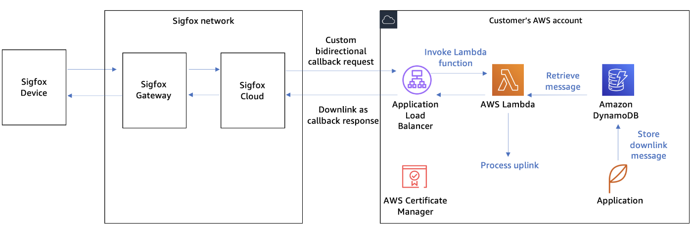
Example architecture for sending downlink data to Sigfox devices
First, AWS customers configure a custom bidirectional callback in Sigfox Cloud. The callback specifies a REST API to be invoked each time an uplink message is sent. The REST API request will forward an uplink message to AWS Cloud. The REST API response can optionally contain a downlink payload. If the downlink payload is available in callback response, the Sigfox Cloud will send it to the Sigfox device.
To implement a REST API endpoint, AWS customers can use an Application Load Balancer with a TLS certificate managed by the AWS Certificate Manager service. The Application Load Balancer can specify an AWS Lambda function as a target. Each time the REST API is invoked, the Lambda function will check if new downlink messages for the Sigfox devices are available and return a downlink message payload as a response. Amazon DynamoDB can be used by the customer’s applications to buffer the downlink message for the Sigfox device.
